

8.1 Introduction
The final step in the construction of asphalt pavement is the compaction process. Compaction is the process by which the freshly placed asphalt mat is compressed (or densified) to reduce the in-place air voids in the mat. Compaction is accomplished while the mat is still at elevated temperature directly behind the paver. The initial compaction forces are applied by the paver screed during placement, and the final compaction is achieved by rollers of various types. During the compaction process, aggregate particles in the mat are reoriented closer and closer together and locked into place to provide a strong skeleton for the asphalt mixture.
Compaction is the most important factor in the performance of a flexible pavement. Adequate compaction of the mix increases fatigue life, decreases permanent deformation (rutting), reduces oxidation or aging, decreases moisture damage, increases strength and stability, and decreases low-temperature cracking. Research and experience have consistently shown that asphalt mixtures that are constructed with marginal materials but well compacted have a good opportunity to perform acceptably. However, mixtures that use top-quality materials and have great volumetric designs but are poorly compacted are more prone to poor performance. Therefore, it is important for an agency to include a density requirement in their specifications that results in a consistent, optimum air void content after compaction.
Compaction is the most important factor in the performance of a flexible pavement.
8.2 Definitions
It is important to understand the terminology associated with asphalt pavements. The following definitions are offered.
Compaction—the process that reduces the volume of an asphalt mixture, shrinking its air voids and reorienting its aggregate closer and closer together, inducing aggregate interlock. This forms what is known as the aggregate skeleton of a mixture, which is its main source of strength.
Density—the mass of a material per unit volume. In the asphalt pavement community, the term density is usually inferred to mean relative density.
Laboratory density—a calculated value that multiplies the measured bulk specific gravity (Gmb) by the density of water (62.4 lb/ft3 or 1,000 g/L) at the design air voids, most commonly following AASHTO T 166 or ASTM D 2726.
Theoretical maximum density (TMD)—a calculated value based on the laboratory testing procedure that follows AASHTO T 209. In this test, a sample of an asphalt mixture’s specific gravity with zero air voids is determined; the symbol Gmm is used for this value. To get its density, this value is multiplied by the density of water (62.4 lb/ft3 or 1,000 g/L). This value is often referred to as Rice specific gravity or Rice density if multiplied by the density of water. The test is named after Jim Rice, who was the developer of the testing procedure.
Relative density—the percentage of a reference density. Almost universally, the reference density for asphalt pavements is the TMD.
8.3 Rollers

Watch Video
While the first implement to induce densification is the screed on the paver, it is the rollers that typically do most of the compaction. By far the most common screed types are the vibratory screeds. These will typically be adjustable to maximize their effectiveness. The screed operator should always follow the procedure outlined by the manufacturer of their screed to accomplish this. The density range that can be expected behind a vibratory screed will be around 70 to 90 percent for most mixtures constructed to the proper thicknesses.
There are screeds more commonly found in Europe that are known as high-density screeds. These use tamping bars to achieve higher densities compared to vibratory screeds. However, to get this higher density and to produce the desired smoothness, the paver must move forward at notably slower speeds than are more common with vibratory screed-equipped pavers.
As previously stated, rollers are the tool that does most of the compaction. Rollers come in different configurations. Traditionally, paving crews have used four common types: static steel, pneumatic, vibratory steel, and combination rollers. While these are still common, additional types now include oscillatory rollers and vibratory pneumatic rollers. Additionally, rollers may be equipped with intelligent compaction technology (see Section 8.3.7).
8.3.1 Static Steel-wheeled Rollers
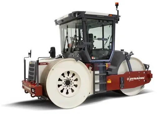
Static steel-wheeled (or static) rollers have steel drums in two different configurations. Double-drum rollers are more common, but a three-wheeled configuration is also available (see Figure 110). One characteristic of the three-wheel and split-drum configuration is that the drum’s rotation speed can change from one side versus the other when steering to reduce tearing or cracking.
Source: Dynapac
Figure 110. Static Steel Roller
The contact pressure from the roller is the main source of compactive energy with steel rollers. Contact pressure is affected by the weight of the roller, typically 3–14 tons (2.7–12.7 t), and their drum width, typically 40–54 inches (102–137 cm). Static rollers usually can be ballasted to increase their mass. Water is commonly used for this purpose. Use of an appropriate antifreeze should be included if freezing is possible.
The weight of the roller is transmitted to the mixture through the contact pressure that is exerted under the drums. Therefore, the contact pressure under the drums should not exceed the supporting capability of the mixture being compacted. Harsher, more stable mixtures used on high-volume highways or airfields may require heavier rollers. Less stable mixtures used for driveways, parking lots, and other low-volume situations may require smaller, lighter rollers. In most cases, the asphalt mat is stable enough to allow the use of rollers with a high contact force.
Because steel-wheel rollers vary in width and weight, a simple calculation can be used to quantify the compactive effort applied by static rollers. By dividing the weight of the roller by the width of all drums, the overall static linear load can be determined, expressed in pounds per linear inch (PLI) or kilograms per centimeter (kg/cm) of roller. For example, an 8-ton roller with two 50-inch drum widths would calculate out to 160 PLI. The PLI can be used to match rollers of different sizes and manufacturers when establishing a rolling pattern. Static, steel double-drum rollers typically provide a minimum of 250 PLI (44.6 kg/cm), and large, three-wheel static rollers typically provide a minimum of 350 PLI (62.5 kg/cm), making them effective breakdown or intermediate rollers.
The two ways to adjust the compactive force of a steel-wheel roller are to adjust the ballast (weight) of the roller and the speed. Adding weight, or ballast, will apply greater force on the uncompacted mixture with each pass. Adjusting the speed affects the dwell time at each location on the mat. Slower rolling speeds raise the dwell time and increase the density increase from each pass of the roller.
All steel-wheel rollers (static and vibratory) used for rolling include a water-spray system and scrapers to moisten the drums to help prevent mix from sticking to the drums. Each drum should be checked for wear on the surface with a metal straightedge and should not be used if grooves or pits have worn into the rolling drum. Also, scrapers should be routinely inspected and replaced if they are excessively worn.
8.3.2 Pneumatic Tire Rollers
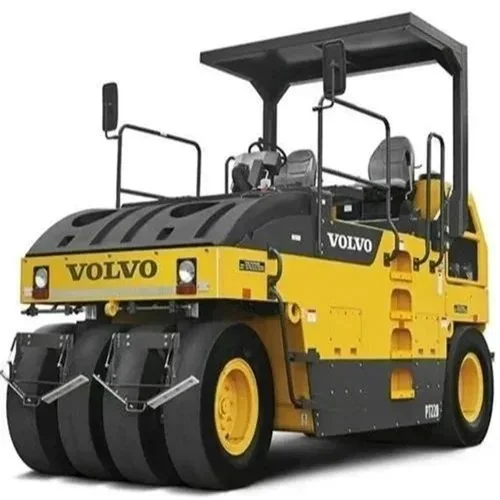
Pneumatic rollers (see Figure 111), commonly referred to as rubber-tire rollers, are equipped with rubber tires instead of steel drums. Typically, rubber-tire rollers are equipped with three to five tires on the front axle and four to six tires on the rear axle. The wheels can move up and down semi-independently of each other. Unlike a steel-wheel roller, the surface of a rubber-tire roller adjusts to the shape of the underlying surface. The intermediate position is the most common phase where pneumatic rollers are used.
Source: Volvo
Figure 111. Pneumatic Roller
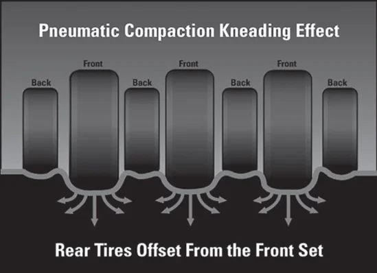
The oscillating wheels and conforming rubber tires result in a constant pressure being exerted across all points of the new mat and a kneading action that manipulates and compacts the mixture differently than a steel-wheel roller. Figure 112 illustrates the kneading action of a rubber-tire roller. The arrows illustrate typical lines of force in the mat.
Source: Asphalt Institute
Figure 112. Forces of Pneumatic (Rubber) Tire Roller
Rubber-tire rollers work well on uneven surfaces, such as leveling courses, as the tires exert a constant pressure and do not bridge over low spots as do the steel-drum rollers. Their kneading action tends to tighten and densify the surface more than steel-drum rollers, thus decreasing permeability. Pneumatic rollers can provide increased density. They tend to be more effective in compacting tender mixes. On tender mixes, their tire air pressure may have to be reduced.
Rubber-tire rollers may be equipped with 15-, 17-, 20-, or 24-inch (380-, 430-, 510-, or 610- mm) diameter wheels and should have smooth tires for asphalt compaction. All the tires should have the same ply rating and the same inflation pressure, preferably the same model from the same manufacturer.
The contact pressure of the tires is calculated as the wheel load divided by the contact area of the tire with the pavement surface. The ply rating of the tire determines the maximum and minimum inflation pressures. Inflation pressure directly affects the contact area and resulting contact pressure. Running the tires at the mid to lower end of the inflation pressure range will help improve the surface texture by sealing the surface. Running the tire inflation pressure higher increases the compactive effort of the roller. Some pneumatic rollers have the capability to change tire pressure and automatically maintain a preset tire pressure while in operation.
There are several ways to adjust the compactive force of a rubber-tire roller. The first is to add or remove ballast. The second is to adjust the tire pressure. The third is to adjust the speed, which affects the dwell time just as in steel-wheel rollers. As was true for static steel rollers, slower speeds increase the compactive effort of each pass.
Pneumatic rollers can be used in the breakdown phase of compaction, but it is the intermediate phase where they see the most usage. Nonuniform subgrade strength can be more evident when rubber-tire rollers are used for breakdown, as the individual wheels can exert high stress on small areas of subgrade weakness that wide, rigid steel drums tend to bridge.
When a rubber-tire roller is used for breakdown rolling, very little horizontal movement of the mixture should occur in the direction of travel. This is because each tire flattens slightly as it drives over the mixture, permitting almost all the compactive force to be exerted vertically on the mat. Excessive horizontal movement of the mix in the direction of travel occurs when the tire diameter is too small, tires are overinflated, or the mix is not stable enough to use a rubber-tire roller for breakdown.
There is some lateral horizontal movement of the mix under a rubber-tire roller, at right angles to the direction of travel. This may cause small bumps or tire marks on the surface that can be rolled out with subsequent passes. Reducing the tire pressure will reduce this lateral displacement. The surface may look irregular, but this appearance is mostly cosmetic.
Desirable rubber-tire roller requirements for breakdown and intermediate compaction are as follows:
- Weight per wheel of 3,000 to 4,500 lbs (1,360 to 2,141 kg).
- A 20-inch (510-mm) minimum wheel diameter.
- Tire inflation pressure of 70 to 75 psi (483 to 517 kPa) when cold and 90 psi (620 kPa) when hot for most mixtures, but the pressure can be reduced if necessary for lower stability or tender mixtures.
Mixture pickup by pneumatic rollers needs to be addressed. Modified mixtures are the most prone to pickup. Preventing or at least reducing the amount of mix pickup by the rubber-tire roller is important. Keeping the tires clean and hot, near mat temperature, is the best way to avoid pickup.
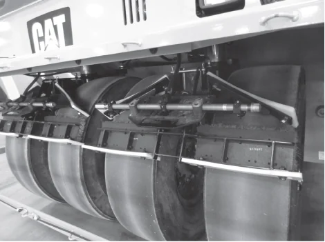
Newer rubber-tire rollers are equipped with a water-spray system that can be used during initial warmup to mitigate mix pickup. Typically, each tire is equipped with a wetting mat that helps distribute the spray water over the tire surface. If pickup occurs, adding small doses of non-foaming detergent or approved water-soluble release agent to the roller water tank may help. All rubber-tire rollers are also equipped with scrapers to remove any materials from tires. Figure 113 illustrates such a system.
Source: Caterpillar, Inc.
Figure 113. Water-Spray System and Wetting Mats on Pneumatic Tires
The operator should strive to get the tires hot and keep them that way before initiating compaction. After ensuring that the wheels are clean, they should run the roller back and forth on a previously placed mat for at least 10 min to warm the tires. Using skirts that surround the tires is encouraged as this will help with both the warming process and keeping the tires warm. If an extended pause in paving occurs, the operator should keep the tires warm by keeping the roller moving as was done during the warmup time.
8.3.3 Vibratory Rollers
Vibratory rollers are the most versatile and common type of rollers used on asphalt. They come in a large variety of configurations. The rollers compact by a combination of weight and vibration of their steel drums. The vibration is produced by a rotating eccentric weight located inside the drum (or drums) and can be adjusted for both amplitude and frequency. These adjustments help to tailor the roller to the mix being paved and its thickness.
Vibratory rollers are the most versatile and common type of rollers used on asphalt.
Source: Dynapac
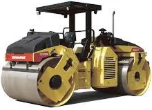
Figure 114. Double-Drum Vibratory Roller
There are two basic models of vibratory rollers: the single drum and the double drum. Typically, single-drum vibratory rollers are used to compact soil or aggregate bases, while double-drum vibratory rollers (shown in Figure 114) are used to compact asphalt. Both drums usually provide propulsion and vary from 3 to 5 ft (0.9 to 1.5 m) in diameter and from 4 to 7 ft (1.2 to 2.1 m) in width.
Static weight, as the term implies, is merely the overall weight of a vibratory roller operating in a static or non-vibratory mode. Vibratory rollers vary in static weight from 2.5 to 18 tons (2.3 to 16.4 t). Widths vary from 40 to 84 inches (102 to 214 cm). Their static weight in terms of drum width is generally from 160 to 180 PLI (29 to 32 kg/cm).
Frequency is the rate at which the vibration impacts generated by rotating eccentric weights occur. Frequency is expressed in vibrations per minute (VPM) or hertz (Hz). Typical frequencies of rollers used for asphalt compaction range from 2,500 to over 4,000 VPM (42 to 67 Hz). The high-frequency drum movement puts the aggregate particles in the mixture in motion, allowing them to slide past one another more easily under the compactive force of the drum. The general rule of thumb is to use the highest frequency setting available. High frequency allows the roller to be operated at a greater efficiency for any forward speed compared to lower frequencies.
Most vibratory rollers are equipped with a VPM indicator or gauge on the control panel that is visible to the operator. With wear and the extreme environment, these gauges can very quickly become out of calibration and inaccurate. A digital or vibratory handheld reed tachometer is a good QC tool that can be placed on the asphalt mat adjacent to the vibratory roller to accurately measure the VPM.
Amplitude is the up-and-down motion of the drum that is caused as the eccentric weight spins inside it. The positioning of weights is adjustable and can be spaced uniformly around the axle or entirely on one side. When the weights are uniformly spaced, they are essentially in balance and impart very little centrifugal force to the drum. Repositioning and locking the weights on one side of the axle unbalances the centrifugal force applied to the drum. This unbalanced condition imparts an up-and-down force to the drum that creates an impact force. The higher the amplitude, the greater the vertical force and the greater the impact force exerted on the mix.
While some vibratory rollers may have high and low amplitude settings, newer rollers provide the operator with a range of amplitude settings. Generally, the thickness of the mat, mix aggregate properties, and compactibility of the mixture are all factors to be considered when selecting the proper amplitude setting for a project. It is usually recommended to start with a high frequency and low amplitude and adjust from these settings as needed. As lifts get thicker, around 2.5 inches (65 mm) or more, or with more robust mixtures, then higher amplitude may be warranted at startup. Thin-lift applications that are less than 1 inch (25 mm) in compacted thickness are generally compacted with static rollers or vibratory rollers in static mode.
The number of impacts per foot or meter should be established as a target before compaction begins. This target should never be less than 10 impacts per foot (IPF) (31 impacts per meter). Corrugations or washboarding will result from fewer impacts than this minimum. The typical target range is 10–14 IPF (31–47 impacts per meter).
Modern rollers provide real-time feedback to the operator on amplitude, frequency, and IPF. If a roller does not have this feature, then the desired IPF can be used to calculate the appropriate forward speed manually to achieve the target. For example, if the minimum desired IPF is 12, and the roller’s frequency is 3,600 VPM, the maximum speed of the roller in terms of miles per hour (mph) is calculated as follows:
3,600 VPM / minimum 12 IPF = maximum 300 ft per min, or maximum 3.4 mph
Building a chart such as shown in Table 9 allows an operator to easily see what speed they need to target to achieve the appropriate impact rate. Caution is encouraged when speeds increase even on high-frequency rollers. Their higher frequency advantages are maximized when traditional speeds are targeted.
Table 9. Maximum Roller Speed Versus Drum Frequency (for range of 10 to 14 IPF)
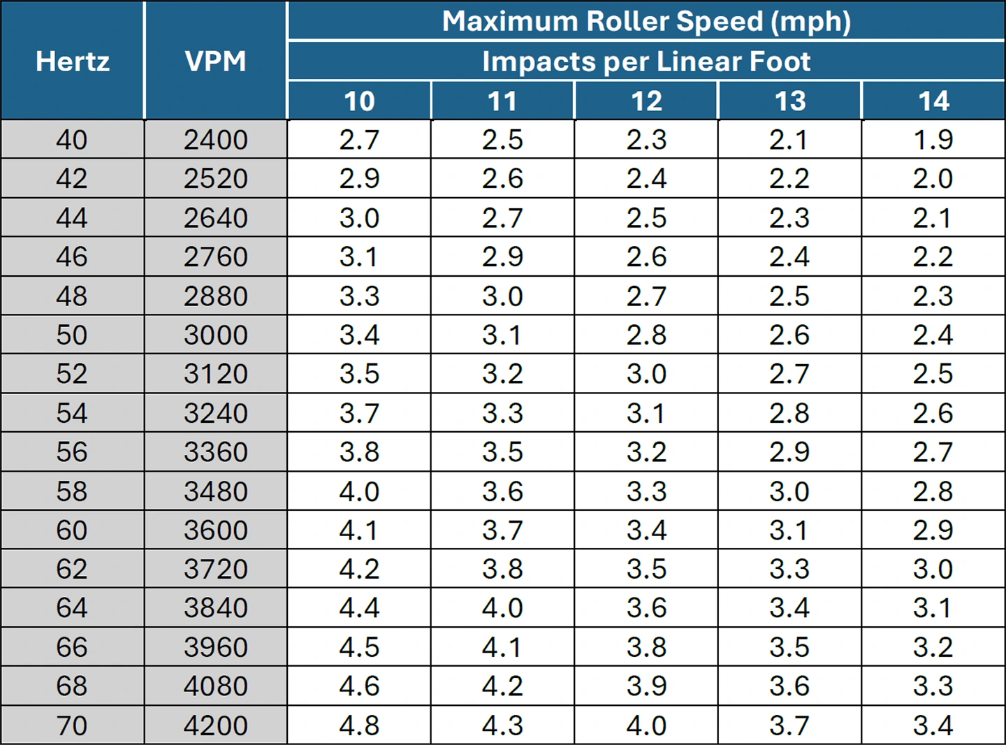
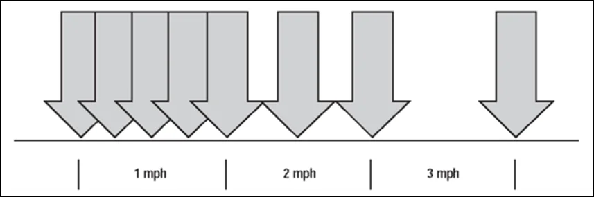
In summary, impact spacing, vibration, amplitude, and roller speed can be used to adjust the compactive effort of a vibratory roller. Slowing the forward speed of the roller decreases the impact spacing, causing the number of IPF to increase. As the speed of the roller increases for a given vibration frequency, the spacing of the impacts grows. The relationship between speed and frequency to obtain a target IPF is illustrated in Figure 115. For asphalt mix compaction, rollers are generally operated at the highest frequency setting available for that roller, with the speed of the roller adjusted to meet the desired impact spacing.
Source: Asphalt Institute
Figure 115. Relationship Between Speed and Vibration Frequency
Vibratory rollers can be operated with both drums, either the front or the back drum, or neither drum vibrating. Each of these options has a situation where it may be preferred. With both drums vibrating, the maximum compactive effort per pass is occurring. This may be used on a stable mixture that requires the most energy to achieve the desired density. Having only the front drum vibrating has the front drum achieving density and the rear drum creating a smoother finish. Switching it up and having the trailing drum vibrating may be a wise choice for a mixture with less stability or more tenderness. Operating in static mode for both drums is usually for thin lifts or when in finishing mode.
Paying attention to the feedback that a mixture provides during compaction can assist in the densification of the pavement, especially with vibratory rollers. For example, a tender mix may respond well to a pass or two in static mode followed by vibrations being initiated to achieve the desired density. However, if conditions change and the mix starts to cool more quickly, the excessive energy used may crush aggregate or de-compact the mixture.
Special attention may be necessary when using a vibratory roller on steep grades. Especially on the initial passes, care should be taken when the roller is traveling downhill to not vibrate and shove the mix down the slope.
8.3.4 Oscillatory Rollers
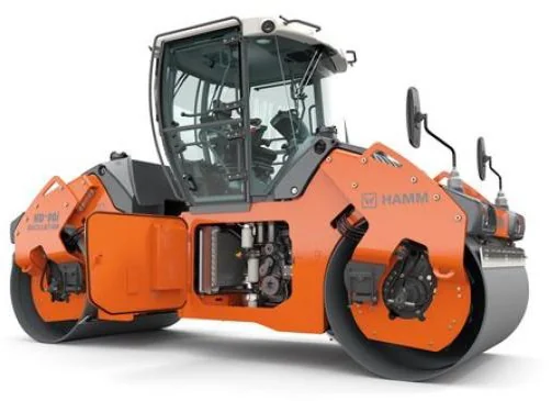
Oscillatory rollers (see Figure 116) have a longer history in Europe, where they were developed, but they are now common tools in the Western Hemisphere too. They are double-drum steel rollers that look very similar to vibratory rollers. An oscillatory roller will typically have an oscillatory and a vibratory drum; some have oscillation on both drums. They are usually used effectively in either the breakdown or intermediate phase. Instead of a mostly vertical compactive force as generated by vibratory rollers, oscillatory rollers are equipped with two vibrating units that operate in synchronization to create a rocking motion in the drum. This rocking motion provides both horizontal and vertical compactive forces that are transmitted tangentially into the asphalt mat.
Source: Wirtgen
Figure 116. Double Drum Oscillatory Roller
Oscillatory rollers exert lower vertical impact forces than vibratory rollers, which may be desirable where there are concerns of damaging nearby infrastructure. Some examples are bridge decks or where underground utilities, especially older ones, are not very deep. Using an oscillatory roller to compact a longitudinal joint can also be very effective. The less aggressive kneading action from an oscillatory roller has been shown to achieve high-density readings with less potential for any tearing of the mat. Moreover, when a mixture is struggling to respond favorably to vibratory rollers, or at lower mixture temperatures, an oscillatory roller may be effective.
8.3.5 Combination Roller
Combination rollers have two different roller types (static steel-wheeled or vibratory steel-wheeled and pneumatic [rubber-tired]) on the same roller (see Figure 117). The most common type of combination roller is equipped with a vibratory drum on the front and pneumatic rubber-tired rollers on the back. This configuration combines the benefits of a vibratory steel drum with the kneading action of pneumatic tires. They are generally used on smaller paving projects such as parking lots, projects with uneven surfaces (manholes, catch basins, etc.), and projects with steep grades. Some contractors also find them to be useful for the compaction of approaches where their maneuverability can be advantageous.
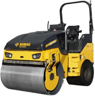
Source: Bomag
Figure 117. Combination Roller
8.3.6 Vibratory Pneumatic Roller
Vibratory rubber-tired rollers, as shown in Figure 118, are pneumatic rollers that have the capability to vibrate the front tires. As is the case with steel-drum vibratory rollers, vibrations are generated by a rotating eccentric weight on shafts along the front axle. Both the frequency and amplitude of the vibrations are controlled independently of roller travel and engine speed. This type of roller provides the benefits of both the kneading action from the rubber tires with the dynamic forces from vibratory compaction. This roller configuration is especially beneficial for intermediate rolling and compacting along confined joints.
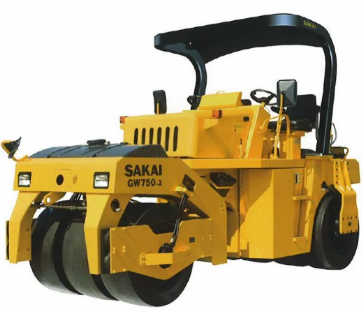
Source: Sakai America, Inc.
Figure 118. Vibratory Pneumatic Rubber-Tired Roller
8.3.7 Intelligent Compaction
Intelligent compaction (IC) is a compaction process that utilizes advanced technology to produce a more consistently densified product. An example of an IC system is shown in Figure 119. An IC roller is a vibratory roller with technology designed to provide better QC during the compaction process. IC rollers incorporate an integrated system to measure stiffness, Global Positioning System (GPS)-based real-time mapping, infrared temperature sensors (front and back), and onboard computers. The computer monitor displays color-coded maps in real time to track roller location, number of passes, surface temperatures, and relative stiffness of compacted materials. The GPS provides extremely accurate roller location data during the compaction process that can be paired with mat temperature and accelerometer data. Roller drums are equipped with accelerometers to measure drum movement during compaction and translate this into an Intelligent Compaction Measurement Value (ICMV). ICMV is a generic term coined by FHWA. It is a real-time measurement of the mixture’s relative stiffness. Five levels of ICMV are currently envisioned, from a relatively basic empirical solution to a mechanistic solution based on dynamic methods and artificial intelligence.
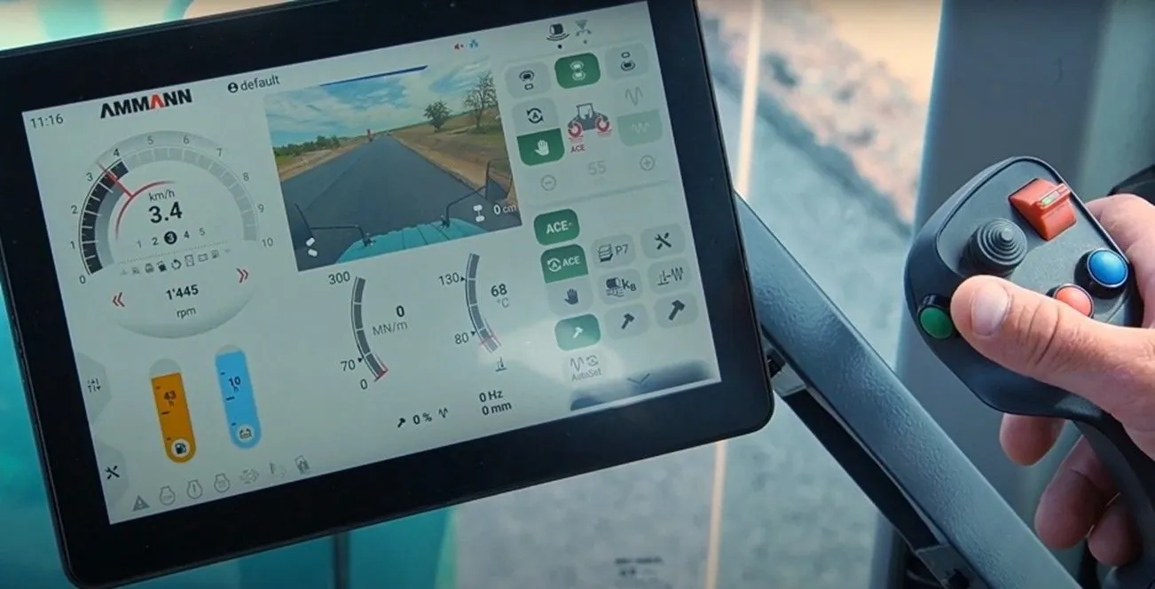
Source: Ammann Group
Figure 119. Roller Equipped with IC Technology
The computer monitor showing a color-coded project map is mounted so the operator can see the ICMV, the mat temperature, and the number of roller passes made during the compaction process. Research and field experience have shown that IC technology will improve the consistency of roller passes and uniformity of compaction simply by providing this critical information in real time to the operator and other project personnel. Figure 120 shows a conventional double-drum vibratory roller equipped with IC technology.
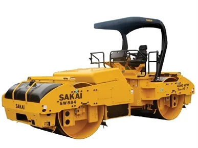
Source: Sakai America, Inc.
Figure 120. Double-Drum Vibratory Roller Equipped with IC Technology
8.4 Factors Affecting Compaction

Watch Video
Many factors have a significant effect on the ability to effectively and efficiently compact asphalt pavements, including the materials used, the mix design, mixture temperature, field operations, and the quality of the materials on which the asphalt is laid. Compaction equipment and the compaction operation itself also have a major effect and will be covered later in this chapter.
The following factors influence the compactibility of an asphalt mixture and will be discussed in the following sections:
- Mixture properties.
- Environmental conditions.
- Layer (lift) thickness.
- Subgrade and bases.
8.4.1 Mixture Properties
The physical characteristics of an asphalt mixture play a significant role in its compactibility. Understanding how these properties affect mix compactibility is important for achieving proper mat density. The specific material properties that are of interest include the following:
- Aggregate properties and gradation.
- Asphalt binder properties.
- Mixture temperature.
8.4.1.1 Aggregate Properties and Gradation
Aggregate gradation, surface texture, and angularity are the primary aggregate characteristics that affect the compactibility of the mixture.
Open-graded mixes are very easy to compact, only seated with a couple of passes; they should not be compacted, or the high void content would close up. The high mastic content of SMA helps compaction, plus the amount of rolldown is less (15 percent compared to 25 percent for dense-graded mixes). While small amounts of natural sand around the No. 30 (0.60 mm) sieve can improve compactibility, excessive sand will increase mixture tenderness and may be difficult to compact. Also, as the maximum aggregate size increases or the amount of coarse aggregate increases, without a corresponding increase in lift thickness, the mixture will be more resistant to compaction.
An increase in surface texture and angularity also makes a mix harder to compact, but it provides for vital vehicle/pavement friction. Crushed, rough-surfaced, cubical aggregate provides more particle-to-particle friction versus round, smooth, natural aggregate, improving long-term performance.
The dust content, or material passing the No. 200 (0.075 mm) sieve, can also affect the compaction process. If the dust content falls below the target percentage from the mix design, the mix can also become tender and hard to compact. If the target value for dust is exceeded, the mix will generally become prone to check cracking during compaction (see Chapter 12, 9).
8.4.1.2 Asphalt Binder Properties
The grade of asphalt binder affects a mixture’s compactibility. Stiffer binder grades require more compactive effort relative to softer grades. Modified binders provide more rut resistance and increase the durability of a mix. Stiffer and modified binders typically require higher compaction temperatures than softer, unmodified binders.
The use of WMA technology can play a role in the compaction process. There are many different WMA additives and techniques on the market. While the purpose of WMA started out to be primarily lowering production and construction temperatures, field studies and practical applications have shown that WMA can also be an effective compaction aid. The effectiveness of WMA as a compaction aid varies with the type of WMA technology used.
8.4.1.3 Mixture Temperature
Since asphalt binder is a thermoplastic material, its viscosity increases as the temperature drops. When the asphalt is fluid (hot), it acts as a lubricant that facilitates compaction of the mixture. As the binder cools, it becomes stiffer and binds the aggregates to the point where the asphalt mat is not compactible.
The temperature of a mixture is key in obtaining density. Asphalt mixtures are most efficiently compacted when they are at or near optimum high temperatures for that mix. Typical starting compaction temperatures are usually in the range of 275 to 310 °F (135 to 155 °C) for both unmodified and modified binders. Due to the wide range of asphalt grades and modifiers, the contractor is encouraged to discuss the appropriate mixing and compaction range with the binder supplier.
In addition, compaction should be completed before the internal mix temperature falls below what is referred to as cessation temperature, typically around 175 to 180 °F (80 to 82 °C). Continuing to compact below these temperatures will typically not significantly increase density and can damage the mat by fracturing the aggregate. This is why most specifications say compaction operations should cease once the mix cools to a certain minimum temperature.
The optimum high and cessation temperatures (see the rolling zone discussion in Section 8.5.3) of a mix will vary from project to project. Therefore, it is important to establish target starting and cessation temperatures at the beginning of each project. The goal of the contractor is to complete the compaction operation and obtain optimum density in that temperature range.
During adverse weather conditions such as cold ambient temperature and/or high winds, the mat will cool more rapidly. In those scenarios, it is sometimes acceptable to raise the starting mix compaction temperature to increase the amount of time to densify the mixture before it cools. However, the increase in temperature should be moderate and never exceed the recommended maximum mixing temperature provided by the binder supplier.
8.4.2 Environmental Conditions
After an asphalt mixture is produced, it is constantly losing temperature. Temperature loss is very slow when it is in a large, bulky state such as a storage silo, an insulated and tarped truck, or perhaps in an MTV. When it is in a windrow, or behind the paver, it is less bulky and losing heat much more quickly. Contractors are forced to work within a specified temperature window to achieve the needed compaction to promote a long-lasting pavement.
It is critical for contractors to understand how environmental factors will affect this window of opportunity. Important factors that come into play include air, surface, and mixture temperatures; wind conditions; overcast versus clear skies; and lift thickness.
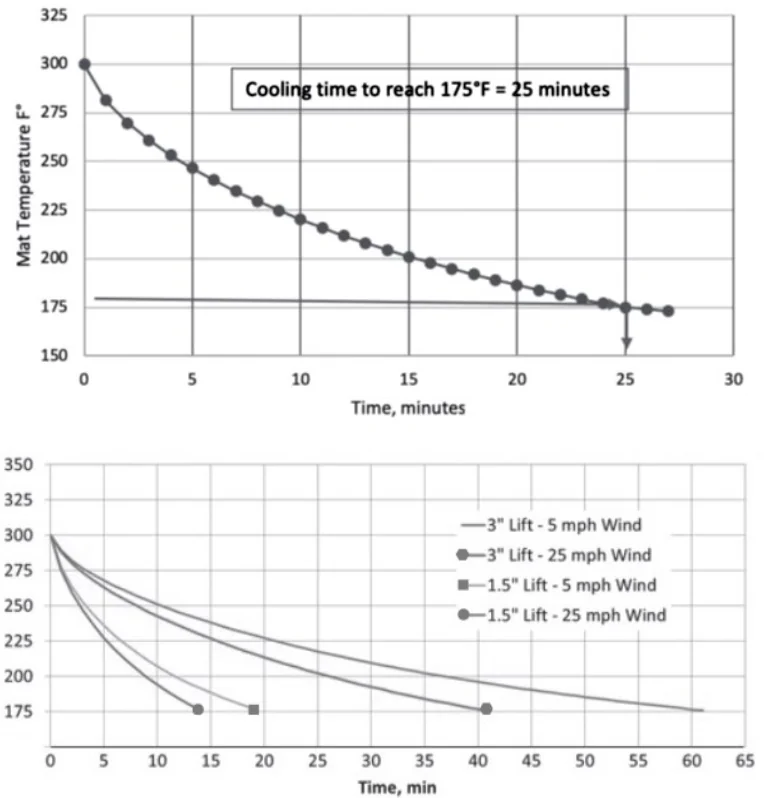
Traditionally, standardized nomographs showed an estimation of time available for compaction. Now, online calculators, software, and mobile device applications provide better job-specific estimations. These more advanced tools consider the binder grade, mixture temperatures, and the mat’s compacted thickness, plus site-specific factors such as latitude, base temperature, and other environmental conditions. Not only are the software tools more accurate, but they also allow for real-time updates as conditions change in the field.
Free software programs such as PaveCool or MultiCool are available online and as mobile apps that predict asphalt pavement cooling during construction. These user-friendly programs estimate how site-specific conditions affect the cooling of a freshly placed mat. The results help contractors plan their rolling operations to achieve target density more efficiently. Actions such as increasing plant mix temperature, covering hauling units, minimizing haul length, shortening windrows in front of pickup machines, etc. can all lessen the rate of cooling. Figure 121 shows typical plots from MultiCool. The lower graph illustrates how 3-inch lifts cool slower relative to 1.5-inch lifts, and how 25 mph winds accelerate cooling relative to 5 mph winds.
Source: MultiCool
Figure 121. Estimating Cooling Rate of Asphalt Mat During Compaction
8.4.2 Layer Thickness
Watch Video
Compacted lift thickness must be considered when planning a paving project. It impacts both the compactibility of the asphalt mat and how rapidly the mat will cool. When the compacted lift is too thin in relation to the NMAS of the mixture, it will be difficult to achieve the required density. The aggregate particles tend to break, especially during vibratory compaction, because there is insufficient room for particle reorientation. Too thin a lift and thus fractured aggregate is a far too common problem.
The recommendation for minimum thickness of a single lift of dense-graded asphalt mixtures is four times the NMAS for coarse-graded mixtures. For fine-graded mixtures, a minimum of three times the NMAS is advised. Fine-graded mixes have a gradation that lies above the MDL, while coarse-graded mixes have a gradation falling below the MDL. Historical pavement thickness guidelines of two times the “top size” are inappropriate for NMAS-defined gradations and are susceptible to poor pavement performance.
The following is an example for a coarse-graded mix with an NMAS of 0.5 inches (12.5 mm):
Minimum acceptable lift thickness = 4×0.5 inches = 2 inches (50 mm) compacted thickness.
Similarly, the following is an example for a fine-graded mix with an NMAS of 0.5 inches (12.5 mm):
Minimum acceptable lift thickness = 3×0.5 inches = 1.5 inches (37.5 mm) compacted thickness.
The time available for a contractor to achieve density is also affected by the lift thickness. Thick lifts, which may be defined as greater than 3 inches (75 mm), have less material exposed to the air and subsurface in relation to their volume and therefore cool slower. Therefore, the contractor will have more time to compact a thicker lift than a thinner option. Also, it is generally easier to achieve the required density of thicker lifts than of thinner ones. Thicker lifts can be utilized when placing highly stable mixtures that are difficult to compact or when paving in adverse weather conditions causes rapid cooling. Thicker layers can permit mixtures to be placed at lower temperatures because of the reduced rate of cooling. Running simulations on PaveCool or MultiCool will provide a clear picture of thickness’ effect on cooling during construction, as was seen in Figure 121.
8.4.3 Underlying Conditions
The subgrade or base (or other underlying material) must be firm and non-yielding under the haul trucks and other construction equipment to provide a solid platform for compaction of subsequent asphalt layers. Subgrades or bases that show movement under trucks or construction equipment will need additional compaction or some type of remedial work to overcome this deficiency before paving. Therefore, it is good practice to conduct proof rolling of the subgrade or aggregate base prior to paving to identify any areas that require corrective action. The remedial work could be one of the many stabilization processes that are available or complete removal and replacement with a more suitable material. Haul trucks may also be limited in size and weight or rerouted where possible to prevent pumping action of subgrade and base materials.
A uniform grade is highly advantageous regardless of the material on which the asphalt is being placed. A nonuniform grade will lead to variable thickness in the asphalt layer. Moreover, high spots from the irregular surface tend to bridge steel-wheel rollers over ruts and other low spots. This will lead to variable densities and uneven grades in those layers. Over time, the nonuniformity that was paved upon will reflect to the surface, compromising its performance.
A best practice is to correct nonuniformity prior to paving. Some of the more common options include properly grading the base or subgrade, milling the existing surface, or placing a leveling lift of asphalt if milling is not an option. All of these options are intended to bring the surface to a uniform grade.
8.5 Compaction Variables Under The Operator’s Control
Watch Video
A number of the primary compaction variables can be controlled during the rolling process by the operator, including roller speed, number of roller passes, rolling zone, and rolling pattern. For vibratory and oscillatory rollers, direction of travel and mode of operation are also under the operator’s control. Each of these factors affects the level of density achieved under the compactive effort applied to the mix.
8.5.1 Roller Passes and Coverages
Each point on a freshly laid mat needs the rollers to pass over it a certain number of times. A pass is defined as a single movement of a roller over any point. Thus, a roller moving in the forward direction over a point (one pass) and then coming back over that point when the roller reverses (second pass) will have made two passes.
Coverages are the number of tracks from one side of an asphalt mat to the other needed to cover the mat once. This is calculated by first determining the effective roller width:

Overlap is the amount of the drum that overhangs previous tracks. This is typically about 4 to 6 inches.
Thus, the equation for the number of tracks for proper coverage will be:

Unless the coverage equation happens to produce a whole number, the answer will always be rounded up to the next whole number.
8.5.2 Roller Speed
Establishing and maintaining roller speeds is critical to getting consistent compaction. The more quickly a roller passes over a particular point, the less time the weight of the roller “dwells” on that point. This in turn means that less compactive effort is applied to the mixture. As roller speed increases, the amount of density gained with each roller pass decreases. The roller speed selected depends on a combination of factors: paver speed, layer thickness, and position of the equipment in the roller train. Target roller speed should always be the lowest pace that will achieve density and allow the paver to maintain a continuous and constant operating speed. In general, roller speeds will be no more than walking speed to accomplish these goals.
As roller speed increases, the amount of density gained with each roller pass decreases.
Once established, the roller speed should not change unless density requirements are not being met. If this happens, the roller will either have to slow down, or additional passes will need to be added. Reviewing the target paver speed should occur if a change in the roller speed or pass count is made. The paver and the rollers always need to be coordinated and balanced with each other.
Having selected a roller speed that balances with the paver speed, the roller should resist speeding up if the paver pulls away. Speeding up may catch the paver, but critical density will be lost due to the faster roller speed.
When using vibratory rollers, impact spacing is determined by the frequency, VPM or hertz, and the roller’s speed, in feet or meters per minute. Recommended impact spacing is 10–14 IPF (31–47 impacts per meter). Falling below this range will produce a washboarding effect, harming the ride quality. When the impact spacing is greater than this, ride quality can also be affected by the formation of ridges in the fresh mat.
The determination of IPF or meter is accompanied by taking the forward speed in either feet or meters per minute and dividing by the frequency. Paving crews are encouraged to predetermine the number of IPF they are seeking and to then calculate the forward speed that will produce this level by using the following equation:

For example, a target of 12 IPF is sought with a roller whose frequency is set at 4,200 VPM. The appropriate roller speed would be:
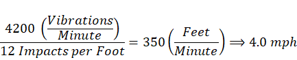
Similarly, if the target was 36 impacts per meter with the same roller setting, the speed would be:

Note that rollers do not only travel forward, but they also need to reverse their directions. They may occasionally need to refill their water reservoirs for the spray system that minimizes the pickup of the fresh asphalt by the drum during a work shift as well. These factors must be accounted for. An “efficiency factor” will have to be applied for these reasons. The typical range for an efficiency factor is 75 to 85 percent (0.75 to 0.85). If the refilling of the water is not needed, then it may be as high as 90 percent (0.90). The equation to do this calculation is:

The effective roller compaction speed is calculated for this roller thusly. The roller is 84 inches wide and the overlap between tracks is 6 inches. The paving width is 14 ft, and the roller efficiency factor is 80 percent.
Apply the roller efficiency factor as follows to determine effective roller speed:


Determine number of roller passes for coverage of the width being pulled:


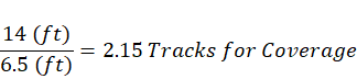
The answer is always rounded up, so in this example, three passes are needed for coverage.
Therefore, for the project described above, compacted with the roller specifications described, the roller should be operated at 3.2 mph over three passes to get full coverage.
To check this information against the paver speed, apply the following equation:

The total number of passes will be the number of passes for full coverage (three in this example) times the number of passes established with the test strip. Assuming the passes from the test strips equal five for this example, then the total number of passes will be 15 (3×5).
Therefore, in this example, the paver speed will be:
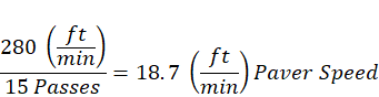
What this says is that the fastest the paver could run, if controlled by compaction, is 18.7 ft/min. If the test strip showed that three passes would achieve the needed compaction, then the calculation would show a paving speed of 31.1 ft/min.
It should be noted that plant production (discussed in Chapter 4) or trucking (discussed in Chapter 6) could control the production–delivery–placement–compaction balance.
8.5.3 Rolling Zone
The “rolling zone” is the temperature range when compaction is accomplished. Compaction must be achieved while the viscosity of the asphalt binder in the mix and the stiffness of the mix are low enough to allow for reorientation of the aggregate particles under the action of the rollers. In other words, the mat must still be hot enough for effective compaction. As discussed in 8.4.1.3, density needs to be achieved before the cessation temperature is reached, effectively halting further densification.
To obtain the required density most quickly, initial compaction should occur directly behind the laydown machine. If the asphalt mixture is stable enough, breakdown rolling can be carried out very closely to the paver while the mat temperature is still high. More density is obtained with one pass when the mix temperature is hotter than after it has cooled.
Sometimes when a tender mix is placed, initial rolling is delayed to avoid excessive shoving or checking of the mix by the rollers. Depending on the mix characteristics, the required density can be achieved if the proper combination of rollers and compactive effort is applied. In those cases, however, when the mix is so tender that rolling must be delayed to the point that the desired density level cannot be achieved, other solutions must be tried. When a tender mix is encountered, the cause of the tenderness must be determined and changes made in the mix production and paving operation to ensure adequate density. Compaction of tender mixes is discussed later in this chapter.
8.5.4 Roller Operations
The improper use of rollers will prove frustrating at best and damaging to the newly laid material at worst. Therefore, it is imperative that the roller operators be properly trained so they will compact the mixture to its appropriate density effectively without harming it.
Compaction is to be done while the mat is in the rolling zone. Rollers will stay with the paver and achieve density if the established roller speed is maintained while getting the needed passes and coverages. The rolling zone is generally broken into three phases: breakdown rolling, intermediate rolling, and finish rolling. Each of these will be discussed further below.
While most contractors have developed roller patterns that consistently work well for them, verifying and altering this standard pattern must be done. Each mixture will behave differently, so the number and types of rollers needed, the number of passes and the corresponding mixture temperatures, and the roller settings will often need to be tweaked. Mixtures vary in their inherent stiffness or tenderness with different binders and aggregate combinations. The longitudinal joint can be especially tough for the contractor to achieve density. The next chapter is dedicated to the joint because of its challenges.
Each mixture will behave differently, so the number and types of rollers needed, the number of passes and the corresponding mixture temperatures, and the roller settings will often need to be tweaked.
Starts and stops of the roller should be done gradually. Starting or stopping a roller too quickly can tear the fresh mat. Stops with steel-drum rollers should be made at an angle to prevent the formation of a bump that will remain even after the completion of all rolling operations. Roller operators should never turn the roller if it is stopped, as this will rip the mat. Also, vibratory or oscillatory rollers will need to have the compaction enhancers turned off when coming to a stop and not reengaged until the roller has sped up from its stop. Modern rollers do this automatically.
The operator must be on the lookout for check cracking. These cracks are generally thin and very shallow. This is discussed further in Chapter 12.
8.6 Determination of Rolling Pattern
Watch Video
The roller pattern is the number of passes and coverages that the respective rollers are seeking in each of the phases of densification. It is a notable challenge for a roller operator to maintain the pattern throughout a paving operation. Use of advanced technology such as IC has been shown to greatly assist this task.
8.6.1 Calculation of Rolling Pattern
The number and type of rollers needed on a project can vary. Regardless of the number of rollers, the basic sequence of rolling for a typical project can be broken down into the following three phases. Preferably, there is at least one roller for each of these phases.
- Breakdown (initial) rolling—the first sequence of passes performed by the roller(s) designated for breakdown on the freshly placed mat.
- Intermediate rolling—all subsequent passes by the roller(s) to obtain the required density before the mixture cools to the cessation temperature.
- Finish rolling—rolling done solely for the improvement of the surface appearance while the mixture is still warm enough to permit removal of any roller marks. Generally, increased density is not expected because of finish rolling.
A consistent roller pattern must be followed to ensure a mat of specified density, shape, and smoothness. The roller pattern dictates which parts of the mat are rolled first and which part is rolled last. Roller patterns will depend on many factors, including paving width, roller width, required number of passes to obtain specification density, and the specifics of the longitudinal joints (confined versus unconfined), as described in the next chapter.
As project conditions change, the contractor must be willing to modify the compaction operation to ensure that target density is obtained. Test strips are intended to evaluate the entire paving operation, from production through compaction. This allows the contractor to demonstrate their ability to meet specifications before going into full production.
8.6.1.1 Breakdown Rolling
The purpose of breakdown rolling is to achieve a high percentage of the target density while the mat is at its highest temperature. This is accomplished by using breakdown rollers with the highest compactive forces that are appropriate for the asphalt mixture type and lift thickness being used on the project.
It is important to start the breakdown rolling operation on the low side of the mat (usually the outside of the lane being paved) and progress toward the high side. The reason is that hot mixtures tend to migrate toward the low side of the mat during compaction. If rolling is started on the high side, migration is much more pronounced than if rolling starts from the low side.
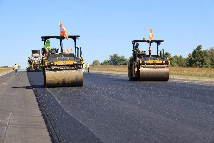
When the asphalt mixture is relatively easy to compact, a single breakdown roller may be sufficient. In scenarios where high production rates dictate high paver speed or where the mix is difficult to compact, two or more breakdown rollers are often used. Figure 122 shows two vibratory rollers working together to speed up the compaction process and increase compactive effort while the mat is at optimum temperature.
Source: National Asphalt Pavement Association
Figure 122. Breakdown Rolling with Multiple Vibratory Rollers
8.6.1.2 Intermediate Rolling
Intermediate rolling should follow breakdown rolling as closely as possible while the asphalt mixture is still well above the cessation temperature. Intermediate rolling should be continuous until all the mix has been thoroughly compacted. Multiple rollers working together can also be used for intermediate compaction, especially on high-production projects where paver speeds are high. Occasionally this phase can be omitted if the breakdown rolling has achieved the needed density.
8.6.1.3 Finish Rolling
Finish rolling is the final phase in the compaction process, done solely to remove roller marks left by breakdown and intermediate rollers so the surface looks good and rides smoothly. Therefore, finish rolling is done at relatively low temperatures, and while the material is still warm enough for removal of roller marks. Vibratory rollers must be operated in static mode when used for finish rolling because the vibrations can damage the cool mat.
8.6.1.4 Compaction of Stiff Mixes
Asphalt mixtures that are properly designed will be reasonably stiff and stable and will require a considerable amount of compactive effort to attain the required degree of density. This type of mix will support the weight of the compaction equipment directly behind the paver. If the mix is placed at a temperature of 275 °F (135 °C) or higher, the rollers will typically be able to compact the mix properly before it cools to a cessation temperature.
Most often, three rollers are used: a breakdown roller, an intermediate roller, and a finish roller. For breakdown rolling, as discussed above, a vibratory steel-drum roller is most often used. For intermediate rolling, a pneumatic tire roller is generally employed, although sometimes a second vibratory or an oscillatory roller is used. Finish rolling is normally done with a static steel-wheel roller or a vibratory steel-drum roller used in static mode.
The breakdown and intermediate rollers should stay close to the paver. If the mix is stable, a bow wave will not occur in front of the vibratory roller drum, and the mix will not exhibit any cracking or checking. With a relatively stiff mix, the finish roller may also be close to the paver since there will be minimal marks from the breakdown and intermediate rollers to be removed.
Because of the internal stability and strength of a stiff mix, more compactive effort may be needed to obtain a given level of density (percent of TMD), but the mix will not creep outward under the compaction equipment during the rolling process. Stiff mixtures of this sort are most commonly found on airfield projects.
For very stiff mixes or when a high degree of density is desired, a pneumatic tire roller may be used for breakdown rolling. For intermediate rolling, a vibratory steel-wheel roller should follow directly behind the pneumatic tire roller, and the finish rolling should be done with a static steel-wheel roller.
8.6.2 Compaction of Tender Mixes
A tender mix is internally unstable, tending to displace laterally and shove while being compacted. Internal mix stability is a function of asphalt binder viscosity, mat temperature, and aggregate gradation and shape. Temperature-induced tenderness is usually one of two types: high-temperature tenderness or midrange temperature tenderness.
8.6.2.1 High-Temperature Tenderness
At high temperatures, some mixes may not be stable enough to support roller loads without laterally displacing. Since this occurs at high temperatures, it is most often encountered by the breakdown rollers when near the paver. Mats exhibiting high-temperature tenderness are typically compacted by merely waiting for the mat to cool to where the asphalt viscosity is high enough to support roller loads. Usually this is enough to solve the problem, but in rare instances the wait period may be so long that the mix cannot be adequately compacted before reaching cessation temperature. Oscillatory rollers have been shown to offer increases in density at lower temperatures than vibratory rollers. If no combination of rollers can successfully achieve density, a new mix design may be warranted. Mixes that exhibit high-temperature tenderness are often susceptible to rutting later in life.
8.6.2.2 Midrange Temperature Tenderness
Some mixes are stable at high temperatures but are unable to support roller loads without laterally displacing at midrange temperatures (typically between 240 °F [115 °C] and 190 °F [90 °C]). The “tender zone” is a term generally associated with this midrange temperature tenderness. There are several theories on the mechanism causing the tender zone, but arguably the most common is that when the mixture is placed, its temperature is relatively hot and uniform throughout. During compaction, the top and bottom layers of the mat cool more rapidly. The middle layer remains hotter and thus is less stiff than the top and bottom of the mat. When rolled in this condition, a steel-wheeled roller tends to push the top portion of the mat laterally past the bottom portion of the mat using the middle portion as a lubricating layer. Additionally, the mix is still fluid enough in the middle portion of the mat to cause the drum to sink into the mat and create a small wave in front.
Several different techniques can be used to compact a mat exhibiting midrange temperature tenderness. First, if done quickly and efficiently, breakdown rolling can be completed before the mat reaches the tender zone. A pneumatic tire roller can then be used during the intermediate phase. Finally, a static steel roller can be used for finish rolling if it is kept off the mat until its temperature has dropped below the tender zone.
8.6.2.3 Causes of Tender Mixes
Tender mixes can also be caused by any one or a combination of these additional factors:
- Excessive moisture content—Excess moisture can come from inadequately dried aggregate or, in the case of an overlay, moisture on or in the existing pavement surface. This moisture decreases the internal mix strength by increasing the liquid content of the mix. As the moisture is converted to steam, it effectively foams the hot liquid asphalt, causing it to expand and push the aggregate particles apart.
- Excess asphalt binder content—At paving temperatures, asphalt binders act as a lubricant during compaction. Mixes with high asphalt content will compact easily but may shove under roller loads.
- Rounded aggregate particles—Rounded particles, found in sands and gravels, tend to slip by one another during compaction, causing distortion and shoving during rolling.
- Excess midsize fine aggregate (between the 0.60 and 0.30-mm [No. 30 and No. 50] sieves)—This can be a result of excessive amounts of natural sands incorporated in the mix design or during mix production.
- Insufficient fines (aggregate passing the 0.075-mm [No. 200] sieve)—During production, dust and extremely fine aggregates become mixed with the asphalt binder and provide a certain amount of stiffness.
- Poor bonding to the existing pavement (for overlays)—If an overlay is poorly bonded to the existing surface, it may act tender as it displaces laterally rather than compacts under rollers. A poor bond can result from not using sufficient tack coat or best practices to apply it.
- Excessive mix temperature—At excessively high temperatures, the asphalt binder may not be viscous enough to support compaction. In some cases, the surface has cooled, but the center of the mix can still be too hot to support rollers. Mixes should generally be placed at an appropriate compaction temperature so rolling can begin immediately behind the paver.
- Compaction techniques—Poor compaction techniques can exacerbate tenderness problems. Quick stops and starts with a steel-wheeled roller will create excessive forces that promote lateral displacement. Operating a vibratory roller in the static mode during breakdown rolling and eliminating quick starts/stops will decrease the potential for lateral mix movement. Generally, mixes that appear tender under a steel-wheel roller will appear less tender under a pneumatic tire roller; therefore, use of a pneumatic roller for breakdown compaction should be considered.
8.7 Roller Checklists
8.7.1 Steel-wheeled Rollers
❑ Does the roller meet project specifications?
❑ Are the steel-wheels smooth, clean, and in good shape (not pitted or chipped)?
❑ Is the roller ballasted, if an option?
❑ Is the release agent tank full?
❑ Is the spray system for the drums functioning properly?
❑ Are the scraper(s) in good shape, clean, and set to function correctly?
❑ If vibratory, are the initial settings for frequency and amplitude appropriate for
the lift thickness?
8.7.2 Pneumatic Tire Roller
❑ Does the roller meet project specifications?
❑ Are the tires smooth, clean, and in good shape (not cracked or marred)?
❑ Are all the tires properly and equally inflated?
❑ Is the release agent tank full?
❑ Is the spray system for the tires functioning properly?
❑ Are the scraper mats in good shape, clean, and set to function correctly?
❑ Is the roller ballasted, if an option?
❑ Are the skirts installed around the tires to retain heat?