

Mat problems can be defined as defects that occur in the asphalt mixture during or soon after the laydown and compaction operations have been completed. These problems fall into two primary categories: 1) equipment-related problems and 2) mixture-related problems. Within each of these two categories, poor workmanship and failure to adhere to best practices lead to many of the mat problems described below. In this section, major mat problems are reviewed, and a description of each problem is presented, including its causes, solutions, and effects on long-term pavement performance. Since segregation can be a serious mat problem, Chapter 10 of this manual is dedicated to this issue.
Table 13 summarizes the mat problems reviewed. The first column lists the various problems, while the remaining columns enumerate possible causes for each. The checks indicate equipment-related causes, while the x’s indicate mix-related causes, which should generally be corrected by changes in the mix design. Provided throughout the discussion of causes are cross-references to earlier sections where greater detail can be found. Note that because of the interaction of various equipment-related and mix-related causes, no attempt has been made to rank the various causes.
Table 13. Mat Problems and Their Causes

Find problem above: ✓ indicates causes related to the paver and X indicates other problems to be investigated
NOTE: Many times a problem can be caused by more than one item; therefore, it is important that each cause listed be eliminated to ensure that the problem will be solved.
12.1 Surface Waves
12.1.1 Description
An asphalt surface can have two types of waves: short and long. Short waves, also sometimes called ripples or auger shadows, are generally 1 to 3 ft (0.3 to 0.9 m) apart, with 1-1/2 to 2 ft (0.45 to 0.60 m) being the most common separation. Long waves are considerably farther apart. The distance between them may correspond to the distance between truckloads of mix. Long waves may also be associated with the reversal points of the compaction equipment, particularly on thick-lift construction or when the mixture being placed is tender and moving longitudinally under the compaction equipment.
An additional type of defect in the pavement surface is a roughness or washboard effect caused by improper operation of a vibratory roller. The distance between these waves is generally very small, typically less than 3 or 4 inches (75 or 100 mm).
Transverse bumps may also appear in new asphalt overlays on top of crack sealants. This is caused by the sliding or shoving of the new mix during the first pass of the breakdown roller.
12.1.2 Causes
A major cause of short waves or ripples is a fluctuating head of material in front of the paver screed. The variation in the amount of mix being carried back to the augers by the slat conveyors and deposited in front of the screed causes the screed to rise and fall as the force pushing against it changes. Too much mix (at the top of the augers) and then too little mix (at the bottom of the augers) being carried in the auger chamber in front of the screed causes the wavy surface as the screed reacts to this variation in force. The fluctuating head of material causes the screed to rotate around its pivot point and “hunt” for an angle of attack. As the angle of attack of the screed changes, the thickness of the mat being placed also changes, and the smoothness of the new layer is directly affected (see Section 7.3.3).
A major cause of short waves or ripples is a fluctuating head of material in front of the paver screed.
Another cause of short waves is a screed that is in poor mechanical condition—one with excessive play in the screed control connections (see Section 7.3). Short waves can also be formed in the mat by improper mounting or sensitivity of the automatic grade control on the paver or by use of an inadequate grade reference device. The problem may also be related to a mobile reference (floating beam) that is bouncing or to the truck driver holding the brakes while the truck is being pushed by the paver (see Section 6.6.1).
Short waves can also be related to the mix design, particularly with a mix that varies in stiffness because of changes in the mix temperature or composition (see Chapter 3). As the stiffness of the mix varies, the forces of the mix pushing on the screed vary as well, causing the screed to rise and fall and resulting in a mat with short waves. Finally, if the mix design is improper in aggregate gradation, asphalt content, mix temperature, or moisture content (the mix is tender), the rollers may shove and displace the mix during the compaction process. However, short waves are typically placed in the mat by the paver because of either its operation or changes in mix stiffness, rather than by the operation of the compaction equipment. Long waves are caused by some of the same variables that result in short waves. Fluctuation in the amount of material in front of the screed and variation in mix stiffness cause the screed to react to the change in the force exerted on it.
If the distance between the wave peaks corresponds to the length of pavement between truckloads of mix, however, the waves may have been caused by incorrectly set hopper flow gates on the paver (see Section 7.2.2) or by the paver hopper and slat conveyors being emptied between loads of mix (see Section 7.2.3). Poor mechanical condition and improper operation of the screed (continually changing the manual thickness control cranks, for example; see Section 7.3.4), as well as incorrectly mounted automatic grade controls (see Section 7.4.2), can cause a long-wave problem. If a stringline is being used as a grade reference, a sag in that line between support posts can also be a cause of long waves (see Section 7.4.2.7). Another factor contributing to long-wave roughness is improper delivery of the mix to the paver, particularly if the haul truck bumps into the paver or if the truck driver holds the brakes while the truck is being pushed by the paver (see Section 6.6.1). One additional factor can be the condition of the underlying surface: the long waves may reflect the waves in the base material.
Long waves may also be found at those points where the compaction equipment reverses direction. This problem is most prevalent when the asphalt layer being placed is more than about 4 inches (100 mm) thick. The problem may be exacerbated when the maximum-size aggregate used in the mix is relatively small compared with the lift thickness. The waves are caused by a bow wave that forms in front of the roller when the mix is tender.
Long waves can be caused by truckload-to-truckload segregation of the mix (see Section 6.4) and by changes in mix temperature (see Section 3.2.5). Both of these deficiencies cause the forces on the screed to vary, resulting in a wavy surface. The compaction equipment can also create a wavy mat if the roller operator turns or reverses the machine too abruptly.
Roughness or washboarding is normally caused by improper operation of a vibratory roller (see Section 8.5). This type of equipment should be operated at a high frequency and corresponding speed to achieve a minimum of 10 IPF; it is, however, generally good practice for rollers not to exceed 2-1/2 to 3 mph (typically walking speed) to ensure sufficient dwell time. The amplitude should be set in relation to the thickness of the layer being compacted—usually a higher amplitude setting for a thicker layer of mix and a lower amplitude setting for a thinner lift. The washboard effect can be worse if the roller is operated at a high speed, particularly if the frequency setting is less than 2,400 VPM.
Transverse bump formation is the result of the breakdown roller creating a bow wave or shoving of the overlay asphalt during the first pass. Heat from the overlay is transferred down into the substrate pavement and crack sealant. The adhesive nature of the crack sealant produces a resistant force greater than the surrounding pavement friction. As the bow wave in front of the breakdown roller passes over the higher-friction adhesive sealant, a reduction in speed of the bow wave occurs and the breakdown roller passes over the bow wave, creating a bump slightly offset from the crack below in the direction of the paving machine.
12.1.3 Solutions
Short waves (ripples) can be eliminated only by preventing their formation. The most important factor in preventing short waves is to keep the amount of mix (head of material) in front of the screed as consistent as possible. In addition, the stiffness of the mix, which is related to both its temperature and its composition, should be maintained as constant as possible. The amount of mix is controlled by properly setting the hopper flow gates and by keeping the slat conveyors and augers operating as much of the time as possible (close to 100 percent) while the machine is moving forward. Mix stiffness is controlled at the asphalt plant by keeping the mix temperature, aggregate gradation, and fluids content (asphalt content plus moisture content) as constant as possible. Any factors that cause either the volume or stiffness of the mix at the screed to change can cause short waves or ripples in the mat.
Short waves (ripples) can be eliminated only by preventing their formation. The most important factor in preventing short waves is to keep the amount of mix (head of material) in front of the screed as consistent as possible.
Surface waves caused by problems with automatic grade controls can be detected by shutting off the grade controls and determining whether the waves continue to form. If the grade controls are at fault, the operation and maintenance manual supplied with those controls should be consulted to determine the proper corrective action. Sags in a stringline reference can be found by sighting down the line as the grade sensor wand passes along the string. Short or long waves caused by the mechanical condition or operation of the paver screed can usually be detected by careful observation of the paver during mix laydown. The long waves formed by incorrect operation of the haul truck or compaction equipment can also be detected easily by observing those operations.
If washboarding is caused by incorrect operation of a vibratory roller, a change should be made in one or more of the following: the vibratory amplitude setting, the vibratory frequency, and the speed of the roller.
Methods to prevent the transverse bumps from crack sealant on the existing surface include the use of asphalt overlay mixtures with high frictional properties such as open-graded mixtures, stone mastic asphalt, or dense-graded mixtures with highly angular and fractured aggregate. Breakdown rolling with the nondriven front drum moving forward tends to push the mixture instead of pulling the mixture under the drive drum. This push creates a larger bow wave in the mixture, often resulting in transverse bumps. Use of a stiffer tack coat and/or allowing the tack coat to completely set to improve the adhesive bond between the overlay and the substrate has also resulted in less overlay shoving and less bump formation.
12.1.4 Effects on Performance
Long-term pavement performance is affected by surface waves, both short and long, in two ways. First, the waves reduce the smoothness of the pavement, which lowers the pavement condition rating or the present serviceability index of the roadway. The structural performance of the pavement will be changed, however, only if the waves are severe enough to increase the dynamic or impact loading of the pavement under aircraft loading or heavy truck traffic. Aircraft are, however, susceptible to excessive vibrations and subsequent component fatigue, particularly in response to long surface waves. Second, short waves and the factors that cause them can affect pavement density levels. A tender mix is generally more difficult to compact properly than is a stable mix; the result may be a decrease in density and a corresponding increase in air void content—leading to a reduction in pavement service life.
Washboarding is basically roughness built into the pavement surface during the compaction operation. Because it affects the degree of density obtained during the compaction process, this type of defect can significantly reduce the long-term durability of the pavement layer. In addition, washboarding contributes to a rough ride for the vehicles using the pavement.
Transverse bumps also contribute to loss in ride quality.
12.2 Tearing (Streaks)
12.2.1 Description
There are three general types of mat tearing or pulling of the asphalt mix under the screed of the paver. The three types are defined by the location of the tear marks in the mat: (a) in the center of the lane, (b) on the outside edges, and (c) across the full lane width.
12.2.2 Causes
A gearbox streak can sometimes be seen in the surface of the mat directly behind the center of the main screed. This streak is typically 6 to 8 inches (150 to 200 mm) wide and is normally caused by a lack of asphalt mix being pushed under the auger gearbox located in front of the center of the screed. This lack of mix may be the result of improper flow gate settings—not enough mix being fed back to the screed. It is more likely to be caused, however, by missing, worn, or improperly set reverse augers or paddles on the augers (located adjacent to the gearbox) that are used to force mix underneath the gearbox (see Section 7.2.2.4).
The rough surface texture is the result of a lack of mix at that point in the pavement width—less mix passes under the screed at the auger gearbox than passes under the screed on either side of the gearbox. The rougher texture, or tearing, makes the surface appear more open or segregated. However, this streak can be a form of segregation when gravity allows the mix from the two conveyors to flow under the gearbox. The surface texture of the mat at that location can be more open than that of the adjacent mix and is generally darker in color. Gearbox streaks are more prevalent with harsher mixes—those containing larger-size aggregate, more crushed aggregate, or lesser amounts of asphalt.
A centerline streak can also be caused by improper setting of the crown on the main paver screed. The appearance of streaks behind the screed is caused primarily by an improper relationship between the crowns at the leading (front) and trailing (back) edges of the screed (see Section 7.3.9). A tearing or open texture several ft (m) wide in the center of the mat may be caused by a lack of lead crown in the screed. Conversely, a tearing or open texture along both outside edges of the asphalt mixture is normally caused by an excess of lead crown in the screed. For most mixes, the lead crown of the screed should be set slightly higher (approximately 1/8 inch [3 mm]) than the tail crown. A proper relationship between lead and tail crowns will result in a uniform texture of the mat across its full width. Edge streaks can be caused by improper flow gate settings or incorrect installation of the screed extensions. Partial width tearing can also result from a cold screed plate if the screed has not been uniformly preheated before paving begins (see Section 7.3.8).
Full-width tearing of the mat can be attributed to a number of factors. One such factor is warped or worn screed plates. Another is the forward speed of the paver being too high for a particular mix. The use of a mixture with aggregate that is large compared with the mat thickness being laid can also be responsible for full-width tearing of the mat. A good rule of thumb for the relationship between the maximum aggregate size in the mix and the minimum compacted course thickness is that the depth of the compacted layer should be at least twice the largest coarse aggregate particle size or three times the NMAS. Thus, a mix containing a maximum aggregate size of 19.0 mm (3/4 inch) (NMAS of 12.5 mm [1/2 inch]) should be placed at least 38 mm (1-1/2 inch) thick. Lastly, cold mix temperatures, particularly when combined with a cold paver screed, can significantly affect the amount of tearing that occurs (see Chapter 7).
12.2.3 Solutions
A gearbox streak can usually be eliminated only by changing the amount of mix being forced under the screed at the auger gearbox. This change is made by installing reverse paddles or reverse augers on each side of the gearbox to push more mix under the gearbox. If the paver is already equipped with such devices, they should be checked to see whether they are worn and need to be replaced.
Constant center or outside edge mat tearing can usually be eliminated by adjusting the relationship between the lead and tail crowns on the paver screed. If this change does not solve the problem, the setting of the paver flow gates should be modified. Full-width tearing can be eliminated by increasing the mix temperature, preheating the screed properly before paving starts, replacing warped or worn screed plates, or increasing the lift thickness.
12.2.4 Effects on Performance
Tearing of the mat affects long-term pavement performance by causing changes in density in those areas where the tearing has occurred. Torn areas may appear segregated and are usually deficient in mix quantity. Pavement performance will be reduced in relation to the degree to which the tearing reduces the density and increases the air void content of the mat. In addition, the torn areas will be more susceptible to raveling and to the effects of moisture (stripping).
12.3 Nonuniform Texture
12.3.1 Description
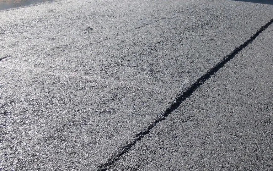
Nonuniform mat texture (see Figure 165) can be described as differences in the appearance of the mix, both transversely and longitudinally, as it is placed and compacted. Normally, minor differences in surface texture will be apparent because of differences in the alignment of the larger coarse aggregate particles as the mix passes out from beneath the paver screed. In addition, a mix with a higher fine aggregate (sand) content will have a more uniform surface texture than a mix containing a larger percentage of coarse aggregate.
12.3.2 Causes
Many factors related to the operation of the asphalt paver affect the uniformity of the surface texture of the mix (see Chapter 7). A variable amount of mix against the screed, caused by overloading the augers or running the hopper empty between truckloads, can cause variations in the amount of mix tucked under the screed and thus produce a nonuniform texture.
Source: National Asphalt Pavement Association
Figure 165. Nonuniform Mat Texture
Improper screed maintenance, including worn or loose screed plates or screed extensions incorrectly installed, as well as low screed vibratory frequency, may alter the mat texture and cause nonuniformity. In addition, a low mix temperature, caused either by plant problems or by the paver sitting too long between truckloads of mix, can be a factor in uneven mat texture, especially if the paver screed is also cold. The tearing that results when the compacted layer thickness is less than twice the dimension of the largest aggregate particles is still another contributing factor.
A soft or yielding base under the course being constructed may cause the new layer to have a variable surface texture (see Section 5.2). Moreover, segregation of the mix caused by poor mix design (Section 3.4.4) or improper handling of the mix during production (Section 4), loading (Section 6.4), hauling (Section 6.5), unloading (Section 6.6), or placing (Chapter 7) operations can contribute to a nonuniform surface texture. The variability of the texture will be affected as well by any factors that cause nonuniformity in the mix, such as deviations in aggregate gradation, asphalt content, or mix temperature (see Chapter 3).
12.3.3 Solutions
The solutions for nonuniform surface texture are as varied as the causes. Paver operation, particularly regarding the need for a constant head of material in front of the screed, should be monitored closely. The paver and screed should both be well maintained and in good operating condition. The compacted thickness of the mat being placed should be designed so that dense-graded mixes have a lift thickness of at least four times the NMAS when compacted. Lift thicknesses for fine-graded mixtures should be at least three times the NMAS.
Finally, a mix that is tender, variable in aggregate gradation or asphalt content, or easily segregated should be modified to increase its stiffness and improve its properties before it is produced at the plant and delivered to the paver for laydown.
12.3.4 Effects on Performance
Nonuniform surface texture is usually associated with nonuniform density. The same compactive effort will generally achieve lower density in areas in which the coarse aggregate has been dragged by the paver screed or segregation of the mix has occurred, as compared with areas having uniform surface texture. As density decreases and air void content increases, the durability and serviceability of the asphalt mat decrease markedly.
12.4 Screed Marks
12.4.1 Description
Screed marks are transverse indentations in the surface of the asphalt mat. They occur when the paver stops between truckloads of mix. Depending on the mixture being placed, some screed marks are barely noticeable, whereas others are very distinct and deep. Screed marks can also occur in the longitudinal direction when rigid or hydraulic extensions are used, and the elevation of the extension is not the same as that of the main screed.
12.4.2 Causes
There are several causes of transverse screed marks (see Section 7.3 for a discussion of screed operations). One is excessive play in the mechanical connections on the screed. Such marks also result when the screed is set up incorrectly and rides heavily on its rear end. If the asphalt mix is tender and if the paver is equipped with a very heavy screed, such as hydraulic extensions with additional rigid extensions attached, the screed will tend to settle into the mix and leave marks. If any of these causes are involved, the screed marks will be visible each time the paver stops.
There are several causes of transverse screed. One is excessive play in the mechanical connections on the screed. Another cause is the haul truck bumping into the paver.
Another cause is the haul truck bumping into the paver when preparing to discharge the mix or the truck driver holding the brakes on the truck when the paver starts to push the truck (see Section 6.6.1). In these cases, the screed marks will appear only when the truck–paver interchange is improper.
Longitudinal screed marks are caused by improper setting of the screed extensions relative to the main screed. When extensions are used, their vertical position shall be set on the same plane and with the same angle of attack as the main screed. If rigid extensions are set at the wrong elevation, a longitudinal mark will occur at the point where the different screed sections are joined. If hydraulic extensions are used, two longitudinal marks may occur—one at the end of the main screed and one at the inside edge of the extension on each side of the machine.
12.4.3 Solutions
If the transverse screed marks are a result of the mechanical condition or improper setup of the paver screed, the screed should be repaired. If the marks are caused by the truck bumping into the paver, the laydown operation should be altered so that the paver picks up the haul truck instead of the truck backing into the paver. In addition, once the paver has established contact with the truck, the truck driver should apply only enough pressure to the brakes to keep the truck in contact with the paver if a truck hitch is not used (see Section 7.2.1).
In some cases, particularly if the mix is very tender, screed marks can be eliminated by not stopping the paver between truckloads of mix. This can be accomplished by using a windrow elevator or MTV to deliver mix to the paver hopper. If dump trucks are used to haul the mix, however, it is generally better to stop the paver between truckloads of material (stopping and restarting the paver as quickly as practical) instead of allowing the paver operator to run the paver hopper dry, reduce the head of mix in front of the paver screed, and increase the opportunity for truckload-to-truckload segregation. In the event the paver stops for an extended period, the operator should use screed assist (boost), which pressurizes the bottom of the screed lift cylinders during stops and thus prevents the screed from settling and causing a dent in the mat.
To achieve a uniform surface texture, the elevation and angle of attack of the screed extensions must be matched to those of the main screed. Longitudinal screed marks caused by improperly setting the elevation of the extensions can be eliminated by correcting the position of each extension relative to that of the main screed. Adjustments to both the vertical position and the angle of attack of the extensions may be needed. These adjustments should be made whenever hydraulic or rigid extensions are used.
12.4.4 Effects on Performance
Transverse screed marks generally are not detrimental to the durability of the mat. They may, however, affect the ride by creating a bump whenever the marks cannot be completely rolled out by the compaction equipment. In many cases, the screed marks have less of an effect on the performance of the mix than does the slowdown and startup of the paver when the operator attempts to keep it moving as the empty truck pulls away and the loaded truck backs into the hopper.
Longitudinal screed marks indicate that the level of the mix under the screed extensions is different from that under the main screed. If the screed marks are severe, differential compaction may occur across the mark or “joint,” with the compaction equipment initially riding on the higher mat. The marks can leave a ridge in the mix if they cannot be completely rolled out.
12.5 Screed Responsiveness
12.5.1 Description
As the thickness control cranks on the screed are changed, the screed’s angle of attack increases or decreases. As the paver moves forward to place the mix, the screed moves up or down to the new equilibrium point for the newly set mat thickness. When the screed fails to respond to changes in the setting of the thickness control cranks, the operator is unable to alter the depth of the layer being placed. The paver also loses its inherent ability, through the principle of the floating screed, to provide the self-leveling action needed to place a smooth asphalt mat.
12.5.2 Causes
An extremely high paver speed (more than 83 ft [25 m] per min for thin lifts or more than 50 ft [15 m] per min for layers more than 2-1/2 inches [63 mm] thick) may cause a lack of responsiveness of the screed (see Section 7.3.4). The mechanical condition of the screed affects its ability to react. The screed riding on its lift cylinders or loose connections on the thickness control cranks will cause the screed to be unresponsive. If automatic grade controls are used (see Section 7.4.2), an incorrect sensor location will render the screed unable to react to input signals from the grade sensors.
If the maximum aggregate size used in the mix is too great compared with the depth of mix being placed, the screed will ride on or drag the largest aggregate pieces. As a result, the screed will be unable to change its angle and will thus be unresponsive to changes in the thickness control settings. Variations in mix temperature will also cause the screed to be unresponsive to changes in the angle of attack because the mix stiffness variations themselves will cause the screed to continually seek new equilibrium levels for the forces acting on it.
12.5.3 Solutions
The paver and screed must be in good operating condition. The sensor for automatic grade controls must not be located either at the tow points or behind the pivot points of the screed; rather, it should be located in the area between one-third and two-thirds of the length of the leveling arms. If the mix texture is uniform (indicating a proper relationship between course thickness and maximum aggregate size), the screed will be able to respond to changes in the thickness control settings.
12.5.4 Effects on Performance
An unresponsive screed causes a rough asphalt mat. The screed is unable to react to manual changes in the thickness settings. It also loses its ability to self-level on an existing pavement surface because it cannot reduce the thickness of the mix placed over the high points in that surface and increase the thickness placed in the low areas.
Thus, the rideability of the course being placed can be affected significantly if the paver screed is unresponsive.
12.6 Surface (Auger) Shadows
12.6.1 Description
Surface (auger) shadows are dark areas that appear in the surface of a mix. In most cases, the shadows cannot be seen until sometime after the pavement has been used by traffic and some of the asphalt binder film has been worn off the exposed aggregate particles by the vehicle tires. Surface shadows are seen most easily when the sun is low on the horizon and the pavement is viewed when looking toward the sun. The shadows are also visible when the pavement surface is damp or when the surface is viewed from the shoulder of the roadway at night and vehicle headlights are shining on the surface.
In severe cases, surface shadows may be visible immediately behind the screed during the laydown operation. Even in this latter case, the shadows will disappear when the mix is being compacted by the rollers, only to be visible again later under the conditions described above. The shadows may be completely across the lane width being placed, or they may be only partially across the width. The extent of the shadows depends on how the paver is operated, particularly the portion of on/off time of the augers on each side of the machine.
12.6.2 Causes
Surface shadows are caused primarily by overloading of the augers on the paver (see Section 7.2.2.4). If the head of material in the auger chamber is large enough to “bury” the augers, the screed will react to the variable forces acting on it. The spacing between the shadows will normally correspond to the starting of the augers when operated in a stop–start manner. Whenever the amount of mix in front of the screed is at or above the top of the augers, the shadows will be formed and seen later in the pavement.
On most pavers it is possible to adjust the distance between the screed and the tractor unit. This is accomplished by unbolting connections on the leveling or tow arms of the paver and moving the tractor forward or backward while the screed remains stationary on the pavement surface. Depending on the make and model of the paver, there is typically 4 inches (100 mm) of adjustment for the screed connection. The severity of surface shadows may increase with the screed in the back position—when more mix is being carried in the auger chamber and the augers are being overloaded. The shadows are thought to be the result of a slight increase in mix density caused by the restarting of the augers and the subsequent forcing of additional mix under the screed. There is no difference in surface texture associated with the location of the surface shadows; they can be seen only from an angle. Their intensity often increases when a tender mix is being laid.
12.6.3 Solutions
The asphalt mixture carried in the auger chamber should be maintained at a level near the center of the auger shaft. This means the flow gates should be set so that the augers operate as close to 100 percent of the time as possible and stopping and starting of the augers is minimized. In no case should the top of the augers be completely covered with mix. Further, the location of the screed should be set as far forward as possible so that the amount of material in the auger chamber is reduced and the head of material in front of the screed is kept to a minimum. The screed should not be set in the back position unless a large-stone mix (one in which the maximum size of the aggregate is more than 1-1/2 inches [37.5 mm]) is being placed.
12.6.4 Effect on Performance
Surface shadows are not necessarily detrimental to the performance of the mix, except for a minor effect on rideability. The difference in the density of the mix in areas with and between shadows is generally not great enough to be determined accurately. The main concern with surface shadows is the visual appearance of the mix to vehicle drivers.
12.7 Poor Precompaction
12.7.1 Description
A modern asphalt paver is normally equipped with a vibratory screed. This type of screed allows the mix to be partially compacted as it passes beneath the screed. Depending on such variables as forward paver speed, layer thickness, mix temperature, and ambient environmental conditions, the density of the asphalt mixture measured behind the screed before compaction is usually around 70 to 90 percent of the TMD (a voidless mix).
A few pavers are equipped with combination screeds, which have both tamper bars and vibrators. At slow paver speeds, the combination screed typically achieves greater compaction of the mix than is obtained with the vibratory screed alone. At paver speeds greater than 25 ft (7.5 m) per min, however, the increased compactive effort achieved with the tamper bar is typically lost, and the degree of compaction obtained is similar to that achieved with a simple vibratory screed.
12.7.2 Causes
The amount of precompaction achieved with the screed decreases as the paver speed increases (see Section 7.3.6). Precompaction generally increases slightly as the frequency of the screed vibration increases. Precompaction decreases significantly, however, if the screed is riding on the screed lift cylinders, thereby limiting the available compactive effort. The level of precompaction obtained is also limited if the mat is too thin for the maximum aggregate size used in the mix (less than four times the mixture’s NMAS for coarse-graded mixes or less than three times the mixture’s NMAS for fine-graded mixes; see the earlier discussion of nonuniform texture), if the mix being placed is too cold, or if the base on which the new layer is being laid is soft and yielding (see Section 5.2).
12.7.3 Solutions
Decreasing the paver speed and increasing the frequency of vibration of the screed should, within limits, increase the level of precompaction achieved during the laydown operation. It is also possible on some pavers to increase the amplitude of the vibration to increase the impact force of the screed on the mix. Proper maintenance of the screed helps as well in obtaining a uniform compactive effort from the screed.
12.7.4 Effects on Performance
If the required density level is obtained using conventional rollers behind the paver, the level of precompaction accomplished by the screed will not affect the long-term performance of the layer. It may be possible, however, to reduce the number of roller passes needed to meet the density and air void content criteria if the amount of precompaction obtained by the screed is higher. In addition, increased precompaction density can reduce the amount of differential compaction that occurs in low spots and rutted areas.
12.8 Joint Problems
12.8.1 Description
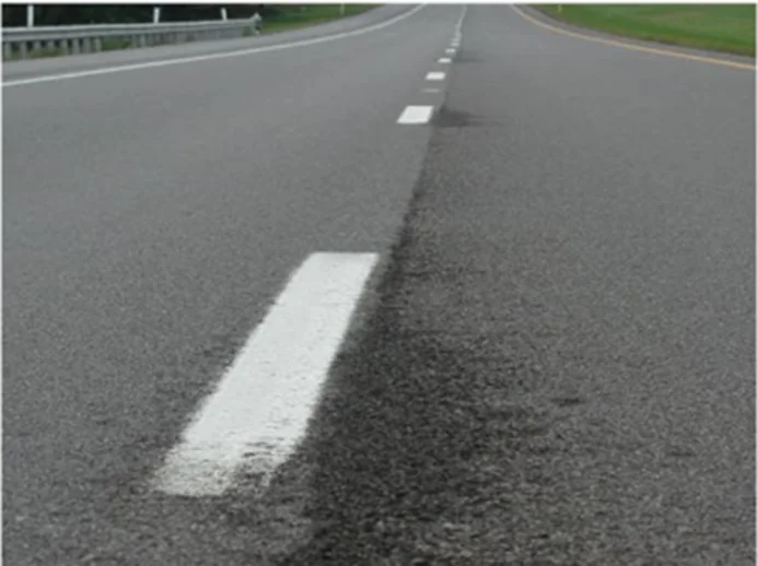
Poor transverse joints are associated either with a bump at the joint, a dip in the pavement surface several feet (meters) beyond the joint, or both. Poor LJs (see Figure 166) between passes of the paver are usually characterized by a difference in elevation between the two lanes, by raveling of the asphalt mix at the joint, or both. The area adjacent to the LJ is usually depressed below the level of the surrounding pavement surface.
Source: Asphalt Institute
Figure 166. Poor Longitudinal Joint Due to Unsatisfactory Construction
12.8.2 Causes
Joint problems are caused by poor construction of the joint, inadequate compaction of mix placed along the joint, improper startup procedures when paving resumes after a stoppage, or improper construction and removal of tapers.
12.8.3 Solutions
One key to a good transverse joint is to construct the joint at the end of the paving day at a location in the mat where the layer thickness is constant (see Section 9.2 for a discussion of joint construction). This means the compacted thickness of the mat at the end of the paver run is the same as that of the previously placed mat. For airfields, a good point is at the end of the pavement, since this will eliminate a transverse joint.
At the start of paving the following day, the paver screed should be placed on blocks on the cold side of the transverse joint. The thickness of the blocks should be related to the depth of the course being laid—approximately 1/4 inch (5 mm) thick for each 1 inch (25 mm) of compacted layer thickness. The front edge of the paver screed should then be placed directly over the vertical face of the joint. Once the paver pulls away from the joint, the right amount of mix should be in the right place, and only minimal raking, if any, normally needs to be done. The mix at the joint should then be compacted as quickly as possible.
For LJ construction (see Section 9.3), it is extremely important to compact the edge of the first lane properly. Doing so requires that the vibratory or static steel-wheel roller hang out over the unsupported edge of the mat by about 6 inches. This practice provides the most compactive effort along the unconfined edge without causing undue lateral displacement of the mix along the edge of the pavement.
For LJ construction, it is extremely important to compact the edge of the first lane properly. Doing so requires that the vibratory or static steel-wheel roller hang out over the unsupported edge of the mat by about 6 inches.
When placing the second (adjacent) pavement lane, the end plate on the paver screed should overlap the first lane by 1 to 1-1/2 inches. Minimal raking, if any, should be done on the mix placed over the first lane. The rollers—vibratory, pneumatic tire, and static steel-wheel—should operate on the hot side of the joint and extend over the joint on the cold side by approximately 6 inches. The same number of roller passes should be made over the LJ as over each point in the interior of the HMA mat.
12.8.4 Effects on Performance
A poor transverse joint will not affect pavement performance to any significant degree if proper density levels are obtained by the compaction equipment. A poor ride will usually be the only negative result. An improperly constructed LJ, however, can seriously decrease the serviceability of the pavement structure. A poorly placed and compacted joint will ravel and cause one side of the joint to be lower than the other. FOD from the raveling of the pavement is a huge concern on all airfields. If the density level is too low, the whole pavement layer thickness at the LJ may wear away under the action of traffic. A poor joint will also be porous, allowing water to enter the underlying pavement courses.
12.9 Checking
12.9.1 Description
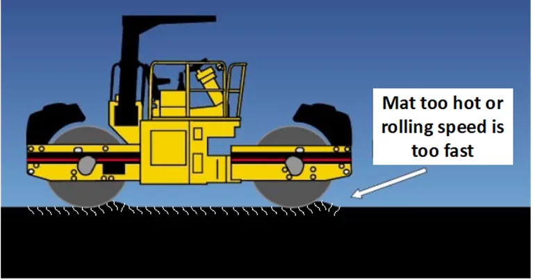
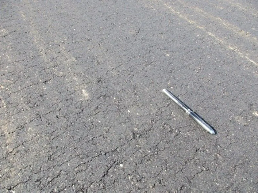
Checking can be defined as short transverse cracks, usually 1 to 3 inches in length and 1 to 3 inches (25 to 75 mm) apart, that occur in the surface of the asphalt mat at some time during the compaction process (see Figure 167 and Figure 168). The checks are not visible immediately behind the paver screed. Rarely does checking occur during the first or second pass of the compaction equipment over the mat except when the mixture is excessively hot. If checking is going to occur, it will normally take place after the mix has cooled to a temperature of less than 240 °F (115 °C) and additional passes of vibratory or static steel-wheel rollers (or both) are made over the mat. Checking does not usually occur when the mix is compacted with a pneumatic tire roller. Most asphalt mixtures do not check at all during compaction, whereas others exhibit tender characteristics and check readily. As checking becomes severe, the cracks become longer and are spaced closer together.
Source: Asphalt Institute
Figure 167. Roller Checking During Compaction
The cracks do not extend completely through the depth of the course but are only 3/8 to 1/2 inch (10 to 13 mm) deep.
12.9.2 Causes
A mix that checks during compaction is a tender mix. The mix shoves or moves in front of the drums on either vibratory or static steel-wheel rollers. Checks or cracks are formed when a bow wave occurs in front of the roller drums as the mix moves longitudinally before the roller reaches that location.
Checking may be caused by two primary factors: (a) excessive deflection of the pavement structure under the compaction equipment (see Chapter 5) and (b) one or more deficiencies in the asphalt mix design (see Chapter 3). A mix that checks is not internally stable enough—does not have enough internal strength at elevated temperatures—to support the weight of the compaction equipment during the rolling process.
Source: National Asphalt Pavement Association
Figure 168. Hairline Cracks Caused by Roller Checking
When a yielding foundation is the cause of the checking problem, the underlying pavement on which the new asphalt layer is being placed is weak and yields under the movement of the compaction equipment. The weight of the rollers causes the layers in the pavement structure to move, shove, and bend excessively, placing the new mix in tension at its surface. The checkmarks are then formed when the surface of the new asphalt is pulled apart as the pavement structure deflects during the rolling operation. The checks should appear in the new mix surface only at locations where there is movement of the pavement structure under the compaction equipment. If the paver passes over a soft spot in the underlying structure, for example, checking should occur only where the soft spot exists.
A more common cause of checking is one or more deficiencies in the mixture: (a) an excess of fluids in the mix—too much asphalt binder or too much moisture in the mix, or both; (b) a hump in the sand gradation curve—too much midsize sand material (1.18-mm and 0.600-mm [No. 16 and No. 30] sieve size) and too little fine sand material (0.300-mm and 0.150-mm [No. 50 and No. 100] sieve size); and (c) a lack of room in the aggregate gradation for the asphalt binder (low VMA).
An excess of fluids in the asphalt mix makes the mix tender and allows it to be displaced easily under the applied compactive effort of the rollers. The mix will be tender if the binder content is too high for the gradation and characteristics of the aggregate used, particularly if the mix has a low VMA content. If the mix contains too much moisture because the aggregate was not completely dried when passing through the batch plant drier or drum mixer, the excess moisture will act as asphalt binder at elevated temperatures and overlubricate the mix. The moisture remaining in the aggregate pores will prevent the binder material from entering those pores in the aggregate, in effect leaving more binder material between the aggregate particles instead of partly inside the aggregate.
If tenderness is due to an excess of asphalt binder in the mix, checking should occur in the mix on a regular, daily basis. If tenderness is due to an excess of moisture in the mix, checking should occur whenever the plant is not being operated properly. For example, checking may occur in the mat the day after a rain, but not the day before. If operations at the asphalt plant do not include removing the extra moisture in the aggregate resulting from the rainfall on the stockpiles, that moisture will add to the asphalt binder fluids and cause the mix to be tender.
A hump in the fine aggregate gradation curve—an excess of midsize sand in the mix—can also cause the mix to be tender. In addition, mixes low in VMA content will generally be tender and move easily under the force of a vibratory or static steel-wheel roller. Further, the various characteristics of the aggregate particles, such as surface texture, angularity, crushed faces, and amount of dust coating, can play a major role in the amount of checking that occurs during compaction. Mixes that are deficient in fine aggregate gradation or lack adequate VMA content will normally check continuously, not periodically. If the sand gradation is variable, however, checking may occur only when the sand gradation is improper. The above mix deficiencies are compounded, and the amount of checking that occurs may be increased, when the mix temperature is too high for the particular asphalt binder grade being used in the mix. As the mix temperature increases, the viscosity of the asphalt binder decreases, causing the mixture to be more tender. An additional factor that can affect the amount of checking is the temperature susceptibility of the asphalt binder itself: the greater the degree of temperature susceptibility of the binder material, the more checking may occur in the mix.
Occasionally, checking can be caused by temperature differentials within a layer of the mixture (heat checking). On a cool day and under windy conditions, the temperature of the mix that is in contact with the existing pavement surface may decrease quickly. The top surface of the mix will also cool quickly. The temperature of the mix in the middle of the layer, however, will remain high. This temperature differential can cause the mix to check under the compactive effort of the rollers.
There are also several secondary causes of checking. One is a mix whose temperature is too high because the mix was overheated in the plant. In addition, improper rolling techniques can cause checking—rolling too fast, stopping too quickly, making sharp turns on the hot mat, or making an excessive number of passes with the finish roller or finish rolling when the mat is still at too high a temperature (see Section 8). Finally, checking may be increased by a poor bond between the new mat and the underlying surface because of a dirty surface or the lack of or poor application of tack coat.
12.9.3 Solutions
If checking is caused by the presence of a yielding foundation underneath the new asphalt layer, the solution is to repair and properly prepare the existing pavement structure before the new asphalt is placed. Soft spots should be removed and replaced. All areas of excessive deflection should be removed and replaced or stabilized. Uniform support is needed in the underlying pavement structure if the new pavement layers are to perform adequately.
If checking is caused by a deficiency in the mix design—an excess of fluids in the mix or a problem with the gradation of the fine aggregate or the VMA content of the mix—the long-term solution is to change the mix properties. Those changes must be made at the asphalt plant and cannot be made at the paving site. If the mix contains an excess of fluids—either asphalt binder or moisture—the binder content should be reduced or the aggregate properly dried to remove all of the moisture. In some cases, the production rate of the plant will have to be reduced for the moisture to be completely removed from the aggregate. In other cases, plant operating conditions may need to be changed (e.g., flights and drum angle). If checking is caused by the gradation of the fine aggregate incorporated into the mix, the gradation should be changed. It may be necessary to increase or decrease the amount of fine aggregate used, add a small amount of fine aggregate with a different gradation, increase the angularity of the fine aggregate, or use a completely different material from a different source. If checking is caused by a lack of VMA in the asphalt mix, changes need to be made to increase the VMA.
Checking is often thought to result from the mix being too hot. This is only partially correct; the mix is too hot at some temperatures to support the weight of the compaction equipment because the mix lacks internal strength and stability. If the mix were properly designed, it would not be too hot to be compacted at any temperature below about 300 °F (150 °C). Most checking occurs when the mix temperature is decreasing from about 240 °F (115 °C) down to about 190 °F (90 °C); rarely does checking occur when the mix temperature is above approximately 240 °F (115 °C) or below approximately 190 °F (90 °C). However, with the use of warm-mix technologies and the number of different warm-mix technologies currently available, these temperatures may vary.
In the short term, changes in both the rolling zone and the type of rollers used to densify the mix can be made to reduce the amount of checking that occurs. If the mix is tender because of excess fluids, a problem with the fine aggregate gradation, or lack of VMA, it may be possible to densify the mix properly at an elevated temperature without causing the checking.
A mix that checks is tender, but this mix can usually be compacted satisfactorily at high temperatures—above 250 °F (120 °C). The required level of density can generally be obtained if enough roller passes can be applied to the mix before it cools to the point at which the checking begins. This can be done by using two breakdown rollers instead of one—using two rollers operating in echelon (side by side) instead of using a breakdown roller followed by an intermediate roller. The two breakdown rollers each apply their compactive effort to one side of the newly placed lane. Many passes are made over each point in the pavement surface before the mix begins to check. Once checking starts, the rolling process is temporarily suspended.
If compaction operations are attempted when the mix is moving, shoving, and checking under the action of vibratory or static steel-wheel rollers, the mix will decompact rather than compact. Rolling should not be carried out with steel-wheel rollers when the mix is tender and checking. Most tender mixes will remain tender until the surface of the mix cools to a temperature of approximately 190 °F (90 °C). At this temperature, the mix has cooled sufficiently so that the viscosity of the asphalt binder has increased to the point where the mix can again support the weight of the compaction equipment. Static steel-wheel rollers can then be used to achieve the final density in the mix and remove any roller marks in the pavement surface.
When a tender mix is in the middle temperature range, between about 240 °F (115 °C) and 190 °F (90 °C), rolling should not be attempted, as discussed above, with either vibratory or static steel-wheel rollers. A pneumatic tire roller, however, can be used in this temperature zone since the rubber tires on this roller will typically not shove the mix and a bow wave will not form in front of the tires. The tender mix will densify, instead of check, under the compactive effort of the pneumatic tire roller. Finish rolling using a static steel-wheel roller can be completed once the mix has cooled to a temperature below about 190 °F (90 °C).
In most cases when checking occurs in the mix, the roller operators tend to back off the mix and allow it to cool. This is the wrong approach to the problem. Delaying the compaction permits the mix to cool and stiffen but most often does not then allow enough time for the mix to achieve the required level of density. With a tender mix, it may not be possible to accomplish both objectives (no checking and adequate density) at the same time if the mix is allowed to cool before rolling operations are started. It is much better to compact the mix as much as possible before checking starts, stay off the mix in the middle temperature zone when checking is most likely to occur, and then finish-roll the mix once it has cooled enough to support the weight of the final roller.
If the mix delivered to the paver is too hot—above 325 °F (165 °C)—it should be allowed to cool after laydown before the compaction process is started. Improper rolling techniques should be corrected. The surface of the underlying pavement should be clean and properly tack coated before placement of the new mix begins.
None of the solutions to the checking problem will work in all cases. Each mix will have its own compaction characteristics. For some extremely tender mixes, checking may occur at a wider range of temperatures, from as high as 270 °F (130 °C) down to as low as 170 °F (75 °C). As noted, mixes that lack internal stability will generally check under steel-wheel rollers (operated in either the vibratory or static mode), and thus these mixes should be redesigned.
12.9.4 Effects on Performance
Although checks extend only a short distance down from the surface, they are highly detrimental to long-term performance because the tender mix characteristics affect the level of density obtained. If the rollers are kept back from the paver in an attempt to decrease the amount of checking that occurs, the level of density obtained by the compaction equipment will normally be reduced significantly. Thus, the air void content of the mat will increase. A mix that contains checks will therefore lack density and have a greatly reduced pavement life under traffic. Additionally, the check cracks themselves are an entry point for water into the mat and an initiation point for later cracking under traffic loads and temperature changes.
12.10 Shoving And Rutting
12.10.1 Description
Shoving of an asphalt layer is displacement of the mixture in a longitudinal direction. Such displacement may take place during the compaction operation or later under traffic. In most cases, shoving during construction is accompanied by a large bow wave in front of the breakdown roller, particularly if that roller is a vibratory or static steel-wheel machine. Shoving may also occur in conjunction with mix checking if the mix is tender enough because of faulty aggregate gradation or excess fluids (asphalt binder or moisture) content. Finally, mat or mix shoving can occur at the reversal point of the rollers, especially at the location closest to the paver. A pavement layer that has shoved under the action of traffic is shown in Figure 169.
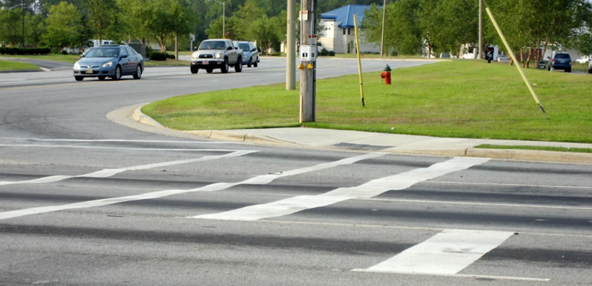
Rutting, illustrated in Figure 170, shows displacement of the mixture in both vertical and transverse directions. Rutting occurs when heavy traffic passes over an unstable mix. In a few cases, the rutting is purely vertical (consolidation rutting). In this situation, the mix (or underlying materials) was not adequately compacted at the time of construction, and the traffic loads are essentially finishing the compaction process. The most common form of rutting is transverse distortion—the mix distorts or shoves transversely as a result of lateral flow of the mix under applied traffic loads.

Source: Asphalt Institute
Figure 169. Shoving Due to Unsatisfactory Mix
12.10.2 Causes
Shoving and rutting are due primarily to an unstable mixture (see Chapter 3). This instability can be caused by the same variables that are responsible for checking—an excess of fluids (asphalt binder or moisture) in the mix, a hump in the fine aggregate grading curve, or the properties of the aggregate and the asphalt cement. Shoving and rutting can be highly prevalent when a sand mix is placed in a thick layer (more than 1-1/2 inch [40 mm]) at a high temperature (more than 280 °F [140 °C]). Further, thicker lifts of an unstable mix in proportion to the maximum aggregate size used will tend to shove more than thinner lifts with the same aggregate size and grading.
Source: East Carolina University
Figure 170. Rutting of Unstable Asphalt Mixture
Improper roller operation, particularly the sudden reversal of the roller, can also contribute to the shoving of the mix during construction (see Chapter 8). If a vibratory roller is run at too great a speed and the impact spacing is too far apart, the mat may develop a washboard effect, where the peak-to-peak distance is equivalent to the impact spacing. Washboarding, or shoving, is more likely to occur at normal frequencies but at high speeds where the impact force is greater. If a pneumatic tire roller with high tire pressure is used for breakdown compaction, a tender mix may shove laterally under the tires. Shoving can occur under any roller that is operated improperly.
Another possible cause of shoving is an excess of tack coat material that may be pulled into the mix. In a similar manner, excess asphalt from a bleeding underlying surface or from joint filler material can be pulled into the mix and increase its fluidity and tenderness. Shoving may occur as well when the underlying surface is dusty or dirty—a slippage failure (see Section 5.5).
12.10.3 Solutions
The solution to a mix that shoves under the compaction equipment is to increase its internal stability. This can be accomplished by reducing the fluids content (asphalt or moisture, or both) of the mix, but only after determining the effect of a change in asphalt binder content on the mechanical properties of the mix. The internal friction can be increased by lowering the mix temperature. Alternatively, the internal friction among the aggregate particles can be increased by changing the aggregate gradation or increasing the amount of angular (crushed) particles in the mix.
The compaction process for a tender mix should be changed, as discussed above under checking, to obtain sufficient density at the time of construction. An increase in the density achieved during the construction process will generally reduce the amount of shoving and rutting that may occur later under applied traffic. Sand mixes, because of their inherent tender nature, should be placed in several thin layers instead of one thick layer when used as base or binder courses.
The compaction equipment should be operated properly so as to reduce the opportunity to displace the mix during the rolling operation. Further, if the underlying pavement surface is dirty, it should be cleaned and a proper tack coat applied.
12.10.4 Effects on Performance
Mats that tend to shove under the compaction equipment are basically unstable. These mixtures will usually continue to distort under traffic, both longitudinally and laterally. Shoving of the mixture during construction is a strong indication that the pavement will rut later and not perform properly under traffic.
12.11 Bleeding And Fat Spots
12.11.1 Description
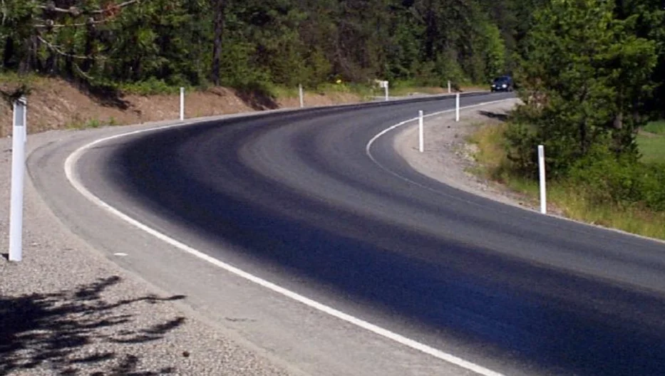
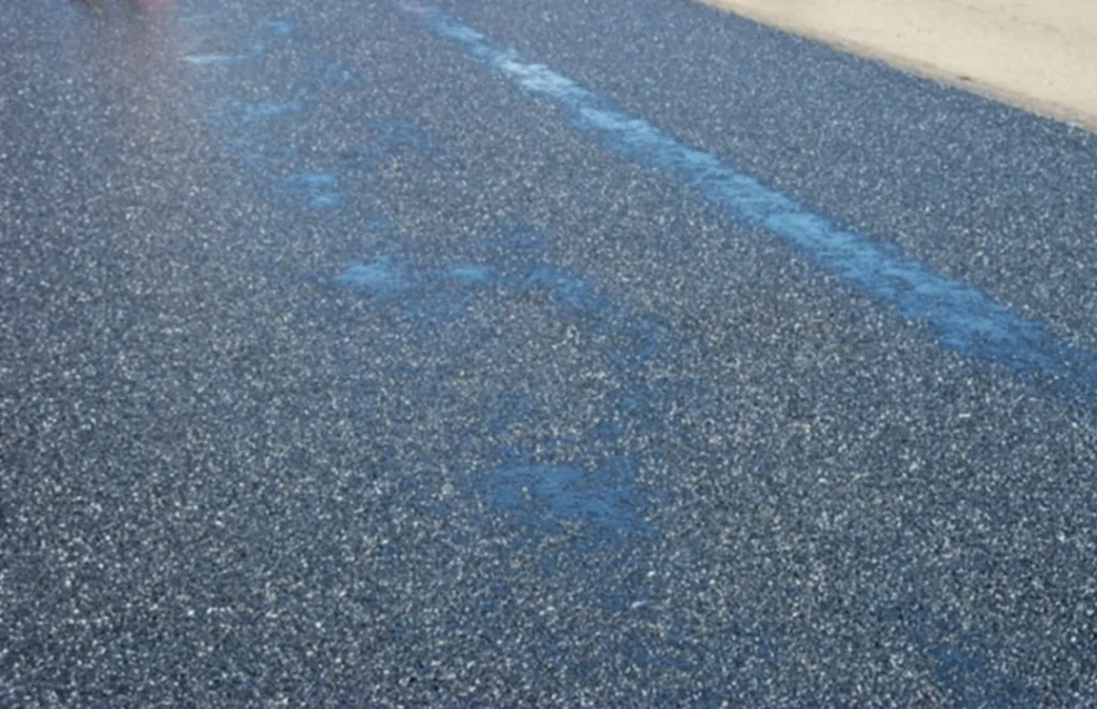
Bleeding of an asphalt mixture (see Figure 171) occurs when the asphalt binder flows to the top of the mix surface under the action of traffic loading. Bleeding is often seen as two flushed longitudinal streaks in the wheel paths of the roadway. Fat spots in an asphalt mixture (see Figure 172) are isolated areas where asphalt binder has come to the surface of the mix during the laydown and compaction operation or later under traffic. These spots can occur erratically and irregularly, or they may be numerous and in a fairly regular pattern.
Source: Pavement Interactive
Figure 171. Asphalt Bleeding in the Travel Lane
12.11.2 Causes
Fat spots are caused primarily by excessive moisture in the mix (see Chapter 3). The problem is more common with mixtures that contain a high percentage of fine aggregate (oversanded mixes) and those that contain aggregates with a high porosity. If all the moisture in the coarse and fine aggregate is not removed during the drying and mixing operation at the asphalt plant, the moisture vapor will force asphalt binder to the surface of the mix behind the paver as the moisture escapes from the mix and evaporates. Fat spots occur more frequently when aggregate stockpiles are wet or when the moisture content varies in different portions of the stockpiles.
Fat spots are caused primarily by excessive moisture in the mix. The problem is more common with mixtures that contain a high percentage of fine aggregate (oversanded mixes) and those that contain aggregates with a high porosity.
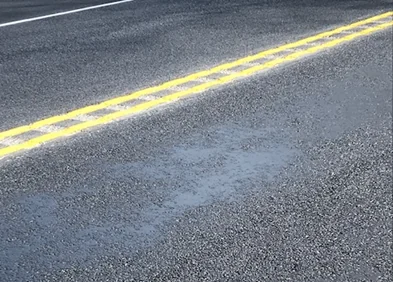
Fat spots sometimes occur in areas where petroleum products, such as oil or diesel fuel, were spilled onto the pavement surface prior to overlay (see Figure 173 and Figure 172) or have contaminated the mix. Use of petroleum-based release agents in the mix haul vehicles can also cause fat spots in the asphalt mix (see Section 6.5.1). In addition, fat spots can be associated with segregated areas in the mix (see Chapter 10). If the mix deposited on the roadway by the paver is segregated, areas in which excess asphalt binder is present in the mix can result in free binder material on the top of the layer being placed.
The causes of bleeding normally fall into two categories. The first is an excess of fluids in the asphalt mixture—either asphalt binder or moisture or both. Under traffic, the extra moisture and asphalt binder will be pulled to the surface by the passage of vehicle tires. This bleeding phenomenon usually occurs on new mix and during hot weather when the viscosity of the asphalt binder is at its lowest level. Typically, the bleeding occurs shortly after traffic is allowed to travel over the fresh mix—while there is still some moisture in the mix and while the viscosity of the asphalt binder is still relatively low.
The causes of bleeding normally fall into two categories: an excess of fluids in the asphalt mixture or a lack of adequate space in the mix for the asphalt binder.
Source: Pavement Interactive
Figure 172. Fat Spot Caused by Localized Excess Asphalt
Source: Asphalt Institute
Figure 173. Fat Spot Caused by Fuel Oil Spill Prior to Overlay Construction
Bleeding may also be associated with a lack of adequate space in the mix for the asphalt binder. If the VMA content and air void content of the mix do not provide enough room for the binder material, bleeding can occur as the mix is densified by traffic, both shortly after construction and later. The traffic compaction process will decrease the air void content of the mix and may, in turn, squeeze some of the asphalt binder out of the mix. The “extra” asphalt will appear as a longitudinal streak or fat spot throughout the length of each wheel path.
One additional possible cause of bleeding is the condition of the pavement layer on which the new mix is placed. If the underlying layer has excess asphalt on its surface or excess crack seal material in the cracks and joints, some of this material may be drawn up through a thin new mix layer. Further, if too much tack coat is applied to the original pavement layer, the excess material may be pulled up through a thin overlay and contribute to the bleeding problem. However, neither of these two causes is common.
12.11.3 Solutions
Variations in the asphalt mix temperature behind the paver indicate that the moisture content of the mix may also be variable. Where moisture has evaporated, the temperature is lower. This latter phenomenon can contribute to both the bleeding of the mix later under traffic and the generation of fat spots in the mix during construction. It is important, therefore, that the aggregate used in the mix be relatively dry and that the moisture content of the mix upon discharge from the asphalt plant be as low as possible, but not more than 0.5 percent. Extra care needs to be taken in drying when producing mixtures that incorporate highly absorptive aggregate.
Bleeding problems caused by excess asphalt binder in the mix can most easily be solved by reducing the binder content, consistent with other properties of the mix, such as air voids, VMA, and strength or stability. Bleeding problems that occur in conjunction with pavement rutting usually can be solved, however, only by a complete redesign of the mixture, with emphasis on proper air void content and VMA criteria.
12.11.4 Effects on Performance
Occasional fat spots in the mix should not affect the ultimate durability of the pavement to a significant degree. The presence of many fat spots, or significant amounts of bleeding in the wheel paths, does affect pavement performance, however, because of variable binder and air void content in different parts of the mix. In addition, other mix problems, such as shoving, rutting, and loss of skid resistance, may occur in a mix that contains many fat areas or areas of bleeding in the wheel paths. The design of the mixture, the operation of the asphalt plant (more complete removal of moisture), or both should be checked to ensure that the mix produced will provide adequate pavement performance under vehicular loading.
12.12 Roller Marks
12.12.1 Description

Watch Video
During the compaction process—whether vibratory static steel-wheel or pneumatic tire rollers are used—longitudinal creases or marks are left in the surface of the mix. Once the mix has cooled to a temperature range of 160 °F to 140 °F (70 °C to 60 °C), these marks are typically removed by the finish roller. Roller marks are indentations that remain in the surface of the mix after rolling has been completed (see Figure 174). With some mixes, pneumatic tire rollers may sometimes leave shadows on the surface of the mix after rolling has been completed (see Figure 175).
Roller marks may also exist in the asphalt surface when any roller is parked on the hot mat for a period of time or when a vibratory roller is vibrated in place. Particularly when used in the breakdown position, pneumatic tire rollers can leave visible longitudinal marks that can still be seen after the finish rolling has been completed. Vibratory washboard marks may be visible if that roller is operated at an improper vibratory amplitude, frequency setting, or speed, as shown in Figure 176.
12.12.2 Causes
Roller marks can be an indication that the proper number of roller passes has not been made over the mix (see Chapter 8).
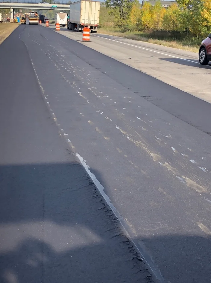
Source: National Center for Asphalt Technology
Figure 174. Roller Marks in a Freshly Laid Asphalt Pavement
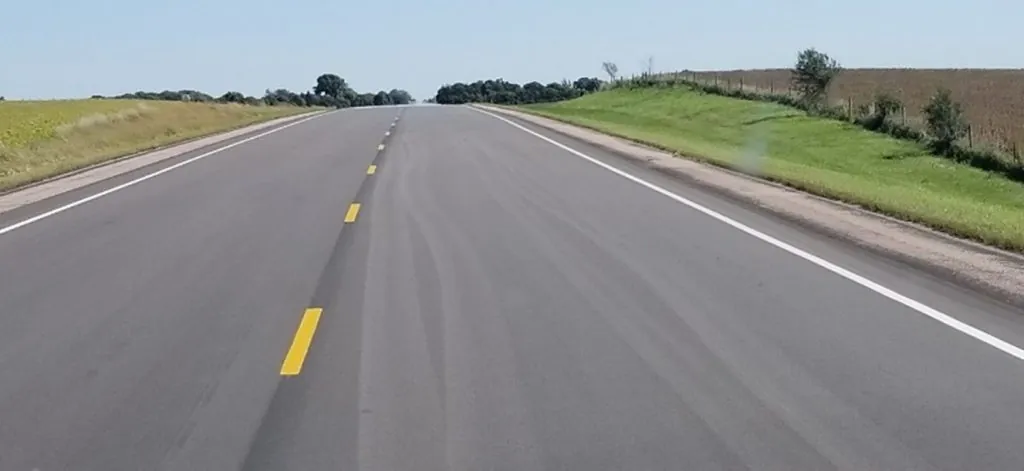
Source: Asphalt Institute
Figure 175. Pneumatic Roller Shadows in a New Asphalt Pavement
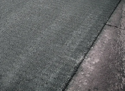
Source: Asphalt Institute
Figure 176. Washboard Marks Left by an Improperly Operated Vibratory Roller
If the compaction process is halted before the required amount of rolling has been completed or if the mix cools before the compaction process has been finished, the longitudinal marks or creases made by the rolling process will remain in the surface of the mix.
Roller marks left in an asphalt layer also may indicate a tender mix (see Section 8.6.2). The roller operator will normally be unable to remove all the marks left by the compaction equipment if the mix is tender or unstable. A tender mix usually will not support the weight of the finish roller until it has cooled to the point at which the viscosity of the asphalt binder has increased enough to stiffen the mix. By the time the mix has decreased in temperature to this point, however, the required level of density can generally no longer be achieved because the mix has lost its workability. For this reason, the roller marks or indentations left during the breakdown and intermediate roller passes usually cannot be removed during the finish rolling process. All the asphalt binder, aggregate, and mix properties that contribute to the formation of a tender mix, as discussed above, also contribute to the inability of the finish roller to eliminate roller marks.
12.12.3 Solutions
If the cause of roller marks is inadequate compaction, additional roller passes should be made with the breakdown, intermediate, or finish rollers to properly densify the mix. The solutions for inadequate compaction related to mix design deficiencies all involve changes to the mix design and to the production of the mix at the asphalt plant. Asphalt binder quality and content, aggregate properties and characteristics, and mix temperature all play a significant role in the workability and stability of the asphalt material under the compaction equipment.
Asphalt binder quality and content, aggregate properties and characteristics, and mix temperature all play a significant role in the workability and stability of the asphalt material under the compaction equipment.
Roller marks normally cannot be removed from a tender mix until the mix temperature has decreased to a relatively low level—usually less than 160 °F (70 °C).
Sometimes it is possible, depending on environmental conditions and the properties of the mix, to remove roller marks left in the mix by using a pneumatic tire roller. If the surface of the mix is hot enough (140 °F [60 °C] or more), several passes with a pneumatic tire roller can be made to “iron out” the surface of the pavement. Finally, roughness or washboarding caused by incorrect operation of a vibratory roller should be eliminated by using proper operating techniques with this equipment.
12.12.4 Effects on Performance
Roller marks are normally an indication that the proper level of compaction has not been achieved. In terms of ultimate pavement durability, the air void content or density of the mix is the single most important characteristic that governs the performance of the asphalt mixture under traffic. If the air void content of a dense-graded mix is high—the density is too low—the pavement generally will not perform well under traffic. Shadows from pneumatic tire rollers have no detrimental effect on performance and will typically disappear soon after the pavement is opened to traffic.
12.13 Poor Mix Compaction
12.13.1 Description
Dense-graded mixtures should be compacted so that the in-place air voids are at an acceptable level. The NMAS of dense-graded asphalt mixtures has a significant effect on the in-place permeability of the mat (see Section 3.5.3). As the NMAS of the mix decreases, the impermeability increases. If not adequately compacted, the mix will be permeable to air and water and will not have the required durability. If the initial compaction results in air voids of approximately 4 percent or lower, the mix may become unstable under traffic after additional densification; the result will be shoving and rutting of the mixture, as discussed earlier. However, the use of polymer-modified binders in these mixtures, coupled with high-quality angular aggregates, will help mitigate this potential for shoving and rutting. Some specialty mixtures using highly modified binders are actually designed for 2 to 3 percent in-place air voids. Most mixes require a significant level of compaction to reach the desired level of air voids.
12.13.2 Causes
When the mix is too stiff or too tender, compaction is difficult. The primary cause of poor compaction is low design mix density (high design air voids), effectively resulting in a mixture with low design binder content (see Chapter 3). Other causes include inadequate underlying support (see Chapter 5), improper type and weight of rollers, improper tire pressure in rubber-tire rollers, improper rolling procedure (Chapter 8), improper mix design (Chapter 3), mix segregation (Chapter 10), moisture in the mix (Chapter 3), variation in mix temperature, and low mix temperature.
12.13.3 Solutions
Solutions to compaction problems include taking the necessary steps to ensure adequate support, producing an acceptable mixture, and using satisfactory laydown and rolling techniques. When support is inadequate, the compaction requirements may have to be relaxed, or the mix may have to be redesigned to allow for satisfactory compaction.
When the asphalt content is too high, the mix may compact too easily, resulting in low air voids (which may lead to rutting; see earlier discussion). When the asphalt content is too low, the mix may be stiff and difficult to compact to the specified density. A satisfactory mix design will produce a mix with optimum asphalt content that can be compacted with reasonable effort to the required density.
Good laydown and rolling techniques, as discussed earlier throughout this manual, are necessary for good compaction. Density can normally be increased by reducing the speed of the paver or rollers. Density can also be increased by increasing the weight and number of rollers. The compaction process must be adjusted to produce optimum density.
12.13.4 Effects on Performance
When the compaction is inadequate, the mix will be permeable to air and water. Water can flow through the asphalt mixture and reduce the strength of the underlying base course. The high voids also result in excessive oxidation of the asphalt mix, which leads to raveling, cracking, and general deterioration of the asphalt pavement over a period of time. A one percent increase in density has been found to conservatively increase the service life of pavement by 10 percent.
When the air voids are excessively low after compaction (less than 4 percent) for dense-graded mixes, the mix is likely to rut and shove under traffic. Again, the use of polymer-modified binders in these mixtures coupled with high-quality angular aggregates will help to mitigate this potential for shoving and rutting. The low voids are not the result of too much compaction but of an unsatisfactory mixture.
12.14 Other Pavement Problems
The above discussion has addressed only those problems that occur at the time of the asphalt mix production, laydown, and compaction. Several other deficiencies can occur on an asphalt pavement structure with time and traffic loading once construction has been completed. Those distresses include fatigue cracking, rutting, shoving, raveling, and disintegration. A discussion of such distresses is beyond the scope of this Handbook.