

7.1 Introduction

Watch Video
The placement operation (also known as laydown or paving) is a critical part of the construction of a quality, long-lasting asphalt pavement. It is important to understand the proper operation of the paving equipment and paving best practices to obtain a durable, smooth-riding pavement that meets the standards of quality construction. Some agencies require the contractor to submit a plan that outlines the practices and procedures that will be used during the laydown process. This is a great opportunity for both the contractor and agency to understand all aspects of the process to meet the agency’s specifications.
A paver is used to place asphalt mixture to the desired width, grade, cross slope, and thickness with a uniform mat texture, thus improving the rideability and smoothness of the roadway. There are two types of pavers-track (crawler) and rubber-tire (pneumatic)-which perform similar functions in a paving operation.
The track paver, on which the tracks may be all steel, steel equipped with rubber pads, or an endless rubber track, offers a high degree of flotation and traction. A rubber-tire paver has a much higher travel speed and is more maneuverable than a tracked paver. When set up and operated properly, both types can place a smooth, uniform mat to meet the required project tolerances.
7.2 Tractor Unit
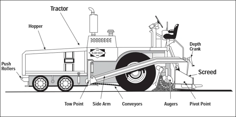
A paver has two primary components: the tractor unit and the screed unit. The tractor unit provides all electrical, hydraulic, and propulsion energy required to complete placement operations in the field. The tractor unit performs the functions necessary to receive asphalt mix from haul trucks or MTVs or to pick up mix with a windrow elevator, carry it through the machine back to the augers, and uniformly distribute the mix across the width of the screed. The tractor unit tows a self-leveling screed unit through the mix as it is placed. The screed provides the initial texture and compaction to the mat as it passes out from under the screed. Figure 79 shows key elements of the tractor and screed units.
Source: Asphalt Institute
Figure 79. Schematic of Asphalt Paver
7.2.1 Push Rollers
The push rollers, located on the front of the paver hopper, are used to maintain contact with the tires of the haul truck and to push it ahead of the paver. The rollers must be clean and rotate freely to allow smooth forward travel of the paver. If the push rollers are not cleaned periodically and do not rotate freely, the truck tires will slide on the rollers and increase the load on the paver. Moreover, if one roller rotates freely and the other does not, the paver may be more difficult to steer.
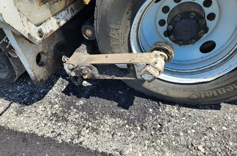
Many pavers are equipped with a truck hitch located underneath or incorporated into the push rollers on the front of the paver, as shown in Figure 80. The purpose of the hitch is to keep the truck in contact with the paver and thereby prevent the truck from becoming disconnected and inadvertently dumping mix on the pavement in front of the paver. The hitch, which is controlled by the paver operator, has forward-extending arms with rollers attached. The rollers are retracted into the truck tire rim and against the tire itself, preventing the truck from losing contact with the paver during the unloading process. Once the truck bed has been emptied of mix, the truck hitch is withdrawn, and the truck is able to pull away from the paver.
Source: Asphalt Institute
Figure 80. Truck Hitch on Front of Paver
7.2.2 Material Handling System
The material feed system on the tractor unit plays a very important part in producing a consistent, high-quality mat behind the paver. The material feed system typically consists of a paver hopper, slat conveyors, material flow gates, and a pair of augers.
7.2.2.1 Paver Hopper
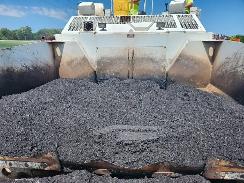
The paver hopper, shown in Figure 81, receives delivered mix and serves as a temporary storage area for material delivered from the haul vehicle, the windrow elevator, or the MTV. The hopper capacity allows the paver to maintain a constant forward motion between loads of mixture being delivered. Mixture delivery methods are detailed in Chapter 6.
Source: Asphalt Institute
Figure 81. Paver Hopper Between Loads
7.2.2.2 Slat Conveyors
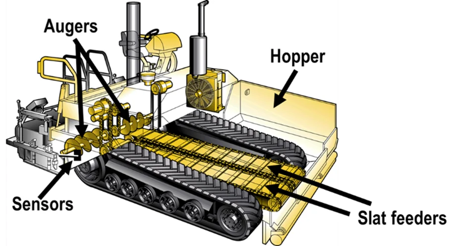
At the bottom of the paver hopper there is typically a set of slat conveyors consisting of heavy chains and flight bars (see Figure 82). The slat conveyors are a continuous system, with the slats being rotated back to the bottom of the hopper underneath the paver itself. These devices are used to carry the asphalt mix from the hopper through the tunnels on the paver and back to the augers. The slat conveyor on one side of the paver operates independently from the one on the other side. The conveyor system operates independently of the speed of the paver and, on most pavers, independent of the speed of the augers. Thus, the amount of mix being carried back through the paver on one side may differ from that being delivered on the other side, and the paver operator can change the feed rate to either side of the paver to pave shoulders, ramps, turnouts, etc.
On some pavers, the slat conveyor system has been replaced by a screw conveyor system. The purpose of this latter system is to remix the mix in the paver hopper and reduce segregation behind the screed.
Source: Asphalt Institute
Figure 82. Material Feed System
7.2.2.3 Flow Gates
At the back of the paver hopper on many pavers is a set of flow gates. These gates, one over each of the two slat conveyors, are used to regulate the amount of mix that can be delivered by each conveyor. The flow gates should be adjusted to provide a uniform head of material (at a level at or just above the center of the auger shaft) in front of the screed. Flow gates are not required when the conveyor and respective auger are independently driven. If more mix is required on one side of the machine than on the other, the speed of the conveyor on that side is increased by the paver operator or by the automatic flow control system to deliver more material back to the augers, thus keeping the head of material in front of the screed consistent. The level of mix in the hopper should always be maintained above the level of the flow gates or tunnel openings at the back of the hopper.
7.2.2.4 Augers
The mix carried to the back of the tractor unit by the slat conveyors is deposited in front of the augers (see Figure 82). Like the two slat conveyors, the augers on each side of the paver are operated independently of one another. The auger on one side of the paver is run in conjunction with the slat conveyor on that same side of the paver. In addition, the paver operator has the option of running the left or right conveyor and auger system in either manual or automatic mode. In automatic mode, a feed control sensor on that side of the machine controls the level of material at the outside edge of the auger. It is extremely important that the augers carry a consistent amount of mix across the front of the screed so that the head of material in front of the screed remains as constant as possible.
It is extremely important that the augers carry a consistent amount of mix across the front of the screed so that the head of material in front of the screed remains as constant as possible.
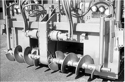
At the junction of the two augers in the center of the paver, adjacent to each side of the auger gearbox, there typically is a differently shaped auger (reverse auger) or a paddle used to tuck mix under the gearbox and ensure that the mix placement at this location is the same as that across the rest of the width of the mix being laid. A paver equipped with a pair of reverse paddles is shown in Figure 83 with the screed removed.
Source: Asphalt Institute
Figure 83. Paver Auger with Reversing Center Flights
If sufficient mix is not placed under the center of the screed and tucked under the gearbox, a longitudinal streak may be seen behind the paver at the center of the screed. This streak can be a form of segregation when gravity allows the mix from the two conveyors to flow under the gearbox. The surface texture of the mat at that location can be more open than that of the adjacent mix and is generally darker in color. This, however, is not always a segregation problem. Rather, the rougher texture and darker color can be caused by a lack of mix placed under the gearbox. When carefully measured, the elevation of the mix in the streak may be slightly below that of the surrounding mix—the streak is actually a low spot in the mat surface. If a gearbox streak is visible at the center of the main paver screed, installation of a reverse auger or paddle system on the paver must be verified. If the reverse augers or paddles are present, adjustments should be made to tuck more mix under the gearbox; worn augers or paddles should be replaced as necessary.
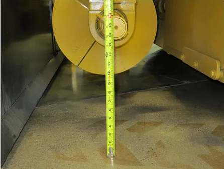
The area around the auger is often referred to as the auger chamber. The auger chamber, shown in Figure 84, is bounded by the front of the screed, the base upon which the mixture is being placed, and the rear of the tractor unit. Modern pavers are equipped with variable height augers that can be changed as needed.
Source: University of Idaho Visual Productions
Figure 84. Auger Chamber
The horizontal distance from the auger to the screed front and the rear of the tractor unit should be equal if possible. A good rule of thumb is to maintain these distances at three times the maximum aggregate size of the mix.
The height of the auger from the base layer is normally set in accordance with the paving depth. A good rule of thumb is to set the distance from the base layer to the bottom of the augers equal to the loose lift thickness plus 2 to 2.5 times the maximum aggregate size in the mix being placed. When auger height is too low, imperfections in the mat texture can appear. The elevation of the bottom of the auger should never be even with or lower than the top of the mix being placed. If centerline segregation is noticeable, raise the augers an additional inch to allow more room for the mix to fill in the center of the auger box.
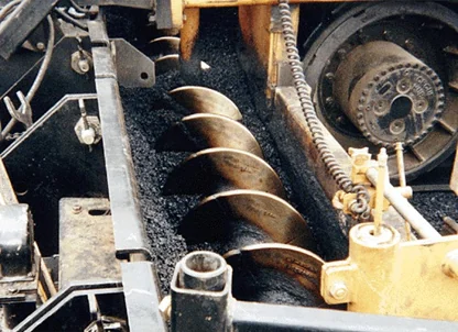
The amount of mix carried in the auger chamber should be as constant as possible. The proper depth of material on the augers is at the center of the auger shaft. The level of material carried in front of the screed should not be so low as to expose the lower portion of the auger flights. Further, the level of mix delivered to the screed should never be so high as to cover the upper portion of the auger. This constant level of material in front of the screed must continue all the way past the end of the auger. When paving wider than the basic screed, auger extensions and material confining plates (tunnel extensions) uniformly carry the mixture the full width of the screed. Ideally, the auger and tunnel extensions should be within 12–18 inches (0.3–0.5 m) from the end plate of the screed to minimize segregation and maintain a constant head of material in front of the screed, as shown in Figure 85.
Source: Reway
Figure 85. Uniform Head of Material at Axle Height
If the feed system is set and operating properly, the slat conveyors and augers on each side of the paver will rarely shut off; they will operate in a slow, continuous manner (20–40 revolutions per min). This continuous action of the conveyors and augers is accomplished by setting the proper position for the hopper flow gates (if any) and determining the correct speed setting for the conveyors and augers. The key to placement of a smooth pavement layer is the use of the material feed system to maintain a constant head (level) of material in front of the screed, primarily by keeping the slat conveyors and augers running as close to 100 percent of the time as possible. Intermittent operation of the slat conveyor and auger systems may cause roughness in the mat, as well as auger shadows and ripples in the mat behind the screed.
Material-control sensors precisely control the volume of material (head of material) in front of the screed. The auger/conveyor combinations on both the right and left sides of the paver work independently of each other, requiring separate material-control sensors. The sensors control the movement of material by starting, stopping, or running at variable speeds to furnish the correct volume of material to match the material demand based on the paving width, depth, and speed.
To operate properly, the sensors must monitor the live (constantly moving) head of material to provide a uniform flow of material in front of the screed. Original equipment manufacturers and aftermarket suppliers use different types of sensors and mount them in different positions to monitor and control the flow of material.
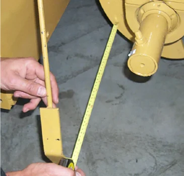
Two common types of material sensors are contact sensors and ultrasonic sensors. Contact sensors use a switching device, such as an on-off switch or potentiometer, that is activated by a paddle arm physically touching the flow of material. As the paddle arm, shown in Figure 86, approaches a near-vertical position, the auger drives start to deliver more mix until the arm reaches a preset angle and shuts off.
Source: University of Idaho Visual Productions
Figure 86. Paddle Switch
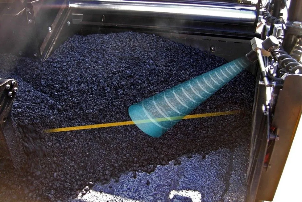
Ultrasonic sensors, shown in Figure 87, are non-contact devices that use sound waves to continuously monitor the face of material being carried in front of the screed. As mix is consumed, the distance being measured by the sensor increases and the auger systems are activated to replenish the volume of mix in front of the screed. To ensure an accurate reading, the sonic beam should be aimed perpendicular (approximately 90 degrees) to the active flow on the face of the mixture. The controller then varies the speed of the conveyors and augers on each side of the machine to maintain a constant level of mix across the front of the screed.
Source: Caterpillar, Inc.
Figure 87. Non-Contact Sensor
As the level of mix in front of the screed rises and falls, the speed of the feed system increases or decreases to maintain a constant level and uniform flow across the width of the screed. For the automatic feed control system to function properly, the feed sensors should be located as close to the outside ends of the augers as possible. If rigid paver screed extensions are used, the control arm should be mounted beyond the ends of the augers, just inside the end gate on the paver screed. If a hydraulically extendable screed is used, the location of the feed sensor control arm should be such that the amount of mix carried in front of the extensions is minimized. In most cases, this means the sensor should be mounted on the end gate of the paver screed and the sensor paddle or wand hung only a short distance in front of the end of the extendable screed.
7.2.3 Hopper Management
The amount of mix in the paver hopper should always be kept at a level above the top of the flow gates or tunnel openings at the back of the hopper. Doing so permits the paver operator to keep the conveyors on the paver full and thus maintain a constant head of material in front of the paver screed. This practice is particularly important between truckloads of mix to reduce segregation problems.
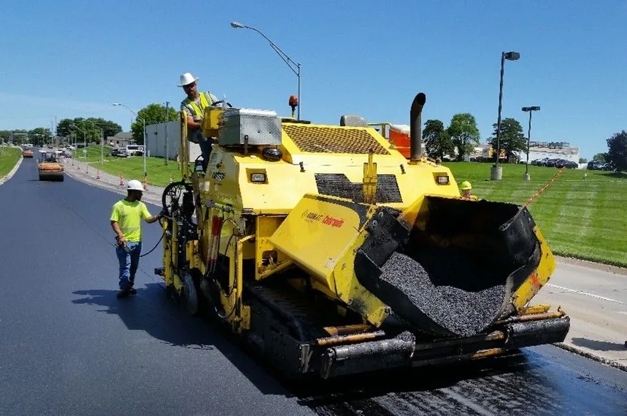
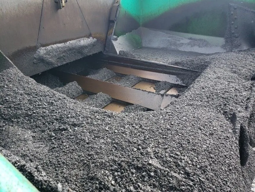
As shown in Figure 88, the sides, or wings, of the hopper are movable. It is considered a best practice to not fold (dump) the wings. However, some paver operators fold the wings of the paver between every load of mix. To prevent spillage of the mix out of the front of the hopper when the wings are folded, the operator often pulls down the amount of mix left in the hopper by continuing to run the slat conveyors, which results in the slat conveyor running empty. This can allow mix to segregate as it trickles down to the conveyor, as illustrated in Figure 89. The material in the outer edge of the wings can become segregated when discharged from the truck. In addition, the mix in the stagnant area of the hopper will begin to cool. This cooling can become significant, especially in cooler weather. This is a perfect formula for the truckload-to-truckload segregation discussed in Chapter 10.
Source: Asphalt Institute
Figure 88. Folding Hopper Wings
Source: Asphalt Institute
Figure 89. Poorly Managed Paver Hopper
To prevent asphalt mix from collecting in the corners of the paver hopper, a fillet can be placed in each corner of the hopper. A triangular piece of sheet steel bolted to the sides of the hopper will prevent mix from being carried in the corners of the hopper. It is also possible to simply not empty the wings of the paver during the paving day. The mix will cool and build up a natural angle of repose. At the end of the day, the cold material is removed from each wing area and transported back to the asphalt plant for recycling.
The best practice is to avoid asphalt mix from collecting or cooling in the wings by using a hopper insert as described in Chapter 6 and using an MTV or window elevator to feed the paver. The steep sides of a hopper insert provide for constant live action focused directly over the slat conveyors and eliminate segregation caused by the paver hopper. This also disconnects the transport vehicles from the paver, reducing dump time and inadvertent contact with the paver. Keeping the hopper full between truckloads of mix helps maintain a constant head of asphalt mix in front of the paver screed and reduces mixture and equipment heat loss. In addition, a paver hopper insert adds material storage, which helps maintain continuous paving.
When it is necessary to fold the wings, the wings should be emptied before the mix that collects in the corners of the hopper has cooled. The sides of the hopper should be slowly raised as soon as the haul truck has been emptied and has pulled away from the paver. A steady forward paving speed of the laydown machine should be maintained as the hopper sides continue to rise. The wings should be fully elevated before the amount of mix remaining in the hopper is lower than the top of the flow gates or the openings at the back of the hopper. The slat conveyors should never be visible at the time the wings are raised-or at any other time during the paving operation. The paver should be stopped before the tunnel openings or flow gates are visible, and the sides of the hopper then lowered.
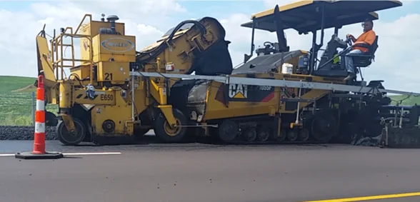
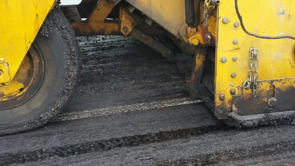
When using a windrow elevator (shown in Figure 90 and Figure 91), the blades on the slat conveyor must be set at the right level to pick up as much of the mix that has been placed on the existing pavement as possible. Essentially, no mix should be left in the windrow, except a minimal amount in the low spots on the pavement surface when a leveling course is being placed. Any thin layer of material remaining will cool quickly and may result in difficulties in compacting the mix. In addition, longitudinal streaks may occur in the mat behind the paver at the same location as the outside edges of the windrow.
Source: Asphalt Institute
Figure 90. Windrow Elevator
Source: Asphalt Institute
Figure 91. Windrow Elevator Picking Up the Entire Windrow
7.3 Screed Unit
Watch Video
The screed unit, which is towed by the tractor unit, establishes the thickness of the asphalt layer and provides the initial texture to the new surface. In addition, through its weight and vibratory action, the screed imparts the initial density into the material being placed.
The concept of the free-floating paver screed was developed in the early 1930s. The design allows the paver screedto average out changes in grade or elevation experienced by the wheelbase (rubber tires or crawler tracks) of the tractor unit. The floating screed concept is employed on all modern asphalt pavers in use today.
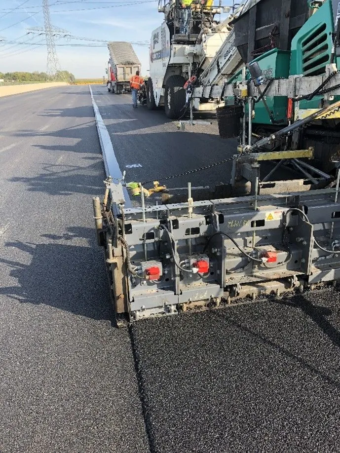
Screeds are classified into two basic types: fixed-width and hydraulically extendable. A fixed-width screed consists of one screed frame that is typically 8 or 10 ft wide. Fixed, bolt-on extensions, shown in Figure 92, must be attached to increase the paving width. Fixed-width screeds are less complex and more rigid, which makes it easier to create uniform layer density from edge to edge when paving wide widths.
Source: Asphalt Institute
Figure 92. Fixed-Width Screed with Vibratory Bolt-On Extensions
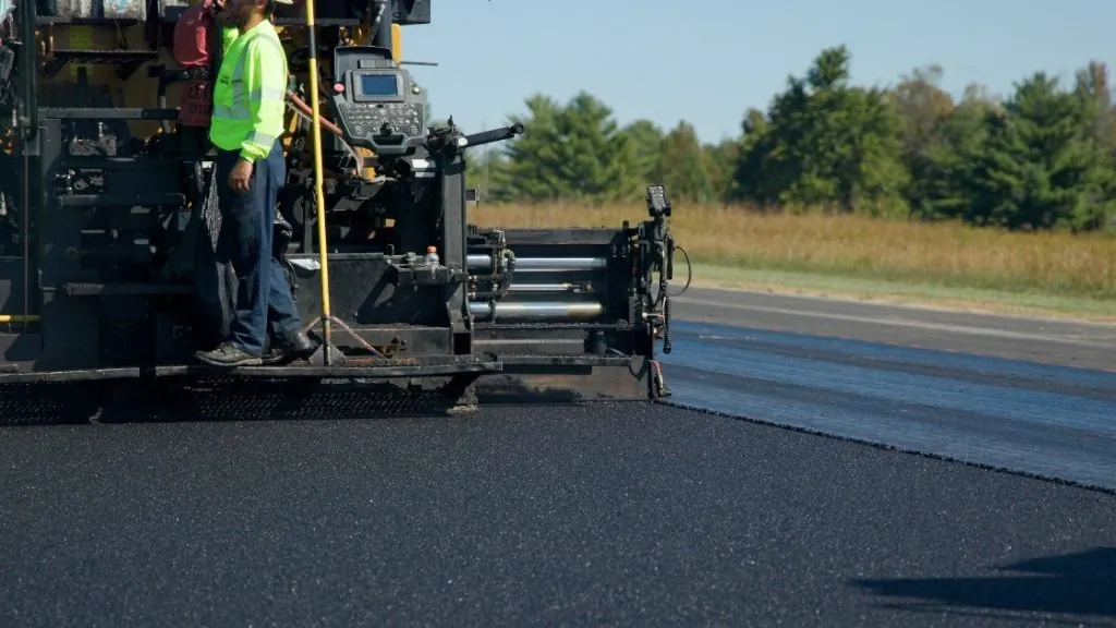
Hydraulically extendable screeds are the most common screed type in use today. Continuously variable widths up to twice the width of the main screed provide increased versatility. Hydraulic screed extensions, shown in Figure 93, are able to pave variable-width pavement sections while the paver is in motion. Lane bump-outs, tapered lanes, and radius sections are just a few examples.
All screed extensions, either fixed or hydraulically extended, must be properly adjusted to place an asphalt mat to the desired thickness, providing a uniform surface across the top of the mat.
Source: National Asphalt Pavement Association
Figure 93. Extendable Screed Paver
Hydraulic screed extensions are mounted in one of two ways, either in front of or behind the main screed. Front-mounted extensions move in and out in front of the main screed. Front-mounted screeds can be retracted more easily than rear-mounted extensions. This is because the front-mounted screeds can displace the head of the mix into the main auger chamber as they are retracted. Rear-mounted screeds must deal with the compression of the paving mix against the end of the main screed as they are retracted. Hence, front-mounted screeds are more often seen on urban-type projects, and rear-mounted screeds are preferred by crews that pave mainline highways and airfield projects that require less frequent width changes.
7.3.1 Tow Points
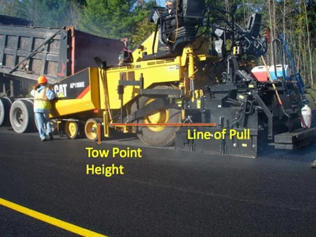
The screed unit is attached to the tractor unit at only one point on each side of the paver. This point, shown in Figure 94, is called the tow (or pull) point. The tow points are pin-type connections that allow the leveling arms (also called side arms, pull arms, or tow arms) of the screed to freely rotate or pivot around those points. The tow points are mounted to the end of a hydraulic cylinder that is fixed to the tractor frame. The height of the tow points can be manually adjusted or controlled automatically by the paver. Automatic screeds are thoroughly discussed in Section 7.4.
7.3.2 Line of Pull
The line of pull refers to the angle at which the screed is pulled forward. A smoother pavement surface is generally placed when the towing force is applied parallel to the final surface that is being placed. Thus, the elevation of the tow points should be set in relation to the thickness of the mat being constructed. Generally, thin lifts of HMA require a lower initial tow point setting, while thick lifts of mix require a higher initial setting.
Source: University of Idaho Visual Productions
Figure 94. Tow Point and Line of Pull
For a relatively thin mat, if the tow point setting is extremely high, the towing forces are applied at an upward angle that increases the lift forces acting on the screed. To maintain a given thickness of material, the angle of attack of the screed must then be decreased to compensate for the increased lift. In this condition, the screed runs at a slightly nose-down angle of attack. Only the front portion of the screed is then compacting and finishing the HMA being placed; the result is poor mat texture and extreme wear on the front portion of the screed plate. In addition, when the paver stops, the screed can have a tendency to rock or teeter as the tractor relaxes the tension on the screed. This may increase the amount of settling of the screed and introduce bumps into the mat.
For a relatively thick mat, if the tow point setting isextremely low, the towing forces are applied at a downward angle that decreases the lift forces applied to the screed. To maintain a given thickness of HMA, the angle of attack of the screed must then be increased to compensate for the decreased lift. In this condition, the screed runs with the rear portion of the screed bearing the majority of the compacting and finishing pressure. This causes poor mat texture and extreme wear on the rear portion of the bottom of the screed plate. Increased control of the forces applied to the screed is gained by setting the tow points in relation to the thickness of the mat being placed.
The floating screed principle is able to operate under manual control. When operated under manual control, it is important that the tow points on both sides of the tractor are at the same level above the base layer. The position of the tow points can be altered by raising or lowering the tow point mounts. For most asphalt mixtures, the tow points are positioned near the middle of the tow point range of movement. For some asphalt mixtures, such as those that are very stiff or very tender, it may be advantageous to raise or lower the elevation of the tow points to improve the texture of the mat being placed.
7.3.3 Forces Acting on the Screed
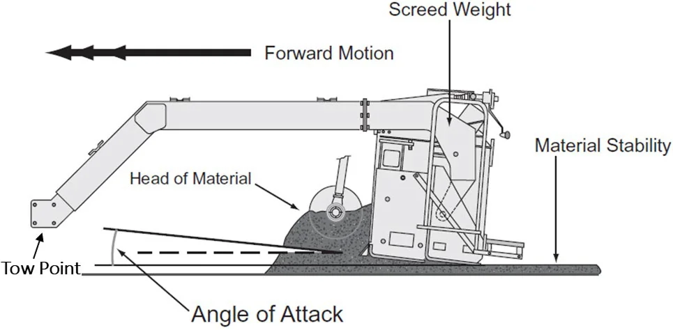
The ability of a free-floating screed to function is the result of the delicate balancing of forces that react on the screed (see Figure 95). The forces on the screed must be in equilibrium (the sum of all forces equal to zero) for the free-floating screed to remain suspended in the mix as it is towed by the tractor unit. The forces exerted on the front of the screed and below the screed are counteracted by the weight of the screed and the angle of attack. When a change in any one force occurs, the screed will rise or fall until it reaches a new equilibrium, and the thickness of the mat being placed will change accordingly.
The forces on the screed must be in equilibrium (the sum of all forces equal to zero) for the free-floating screed to remain suspended in the mix as it is towed by the tractor unit.
Source: Asphalt Institute
Figure 95. Elements That Impact Screed Forces
Many forces impact the screed. It is important to understand those forces that are most easily managed in the field: the angle of attack, paver speed, head of material, and mixture properties (temperature).
7.3.3.1 Angle of Attack
The forward end of the screed tow arms attaches to pivot points at the tow point on the paver. The tow point pivot is always free to rotate as the screed is towed through the mix. There is another pivot at the rear of the tow arms where it attaches to the screed. This screed pivot is locked into position by the thickness control device (screw) located on the screed. The position of this locking screw establishes the angle of attack.
The pitch of the angle of attack contributes significantly to the upward force on the screed and allows the free-floating screed to function. If no other force acting on the screed changes, an increase in the angle of attack will increase the upward component of force acting on the screed. Decreasing the pitch reduces the upward force on the screed. The screed elevation will respond to changes of force until the forces exerted on the screed return to equilibrium.
The tow point elevation and the angle of attack should be adjusted so that there is uniform pressure on the bottom of the screed plate (from front to back) while paving at the desired thickness. If the angle of attack is too low, there will be excessive pressure and wear on the nose of the screed; if too high, that pressure and wear will be on the tail of the screed. Both conditions can result in nonuniform texture problems and roughness in the finished mat surface.
7.3.3.2 Paver Speed
The upward force exerted on the screed changes as the speed of the paver increases and decreases. As the speed of the paver increases, the upward force created by the material passing under the screed is reduced. When this force is reduced, the weight of the screed causes it to fall. If the tow point remains unchanged, the falling screed rotates about the tow point pivot and increases the angle of attack until equilibrium is reached at a new elevation (thinner mat). Conversely, when the paver speed decreases, the friction is increased, creating more force against the screed. The screed rises until the decreasing angle of attack and weight of the screed reach equilibrium with the increased force of the mix. Because the speed of the paver has a major effect on the angle of attack of the paver screed, it is good paving practice to keep the speed as consistent as possible during laydown operations.
Ideally, the speed of the paver should be matched to the production rate of the asphalt plant. Assuming the paving day length is the same as the plant production day, the ideal paving speed is when the paver consumes the mix at the same rate it is produced by the plant.
As an example, if an asphalt plant is producing 300 tons per hr for 10 hrs, it would produce 3,000 tons per day. If the pavement being placed requires 1,000 tons per mi, the plant will produce a 3-mi (15,840 ft) length of pavement. If that length is to be paved in 10 hrs (600 min), the theoretical paving speed would be 15,840 ft divided by 600 min, which equals 26.4 ft per min.
Should the pavement being placed require 1,500 tons per mi, the length would be 2 mi per 10-hr day. In this case, the paving speed is 10,560 ft divided by 600 min, which equals 17.6 ft per min. Every project will be different, but consistent, nonstop paving should be the goal. Section 7.5 provides an in-depth discussion on calculating yield.
As noted previously, to achieve the smoothest possible mat behind the paver screed, it is essential to keep the paver always moving at a constant speed. Running the paver faster than necessary to place all the delivered mix and then stopping to wait for the next haul truck to arrive at the paving site will diminish the quality of the mat.
When the paver needs to be stopped, it should be stopped as quickly and smoothly as possible before the level of mix in the hopper is drawn down below the top of the flow gates or the tunnel openings. This will keep the head of material in front of the screed constant while the effect of the change in the paver speed on the angle of attack of the screed is minimized because of the rapid speed change. The paver operator should return the laydown machine to the desired paving speed as quickly as possible to minimize the effect of the change in paver speed on the angle of attack. It has been found that the “rapid stop, rapid start” procedure for stopping the paver provides for good mat smoothness and consistent mat thickness.
When the paver needs to be stopped, it should be stopped as quickly and smoothly as possible before the level of mix in the hopper is drawn down below the top of the flow gates or the tunnel openings.
It is good paving practice for the paver to remain in one position, with the hopper as full as possible and the head of material constant, until additional mix arrives. If a long delay is expected, consideration should be given to constructing a transverse joint.
7.3.3.3 Head of Material
The head of material is the amount of asphalt mix in the auger chamber that exerts force against the screed. When the head of material changes, the net force acting on the screed also changes. As the forces acting on the screed change, the screed must come to a new angle of attack to compensate for the change in force acting on it.
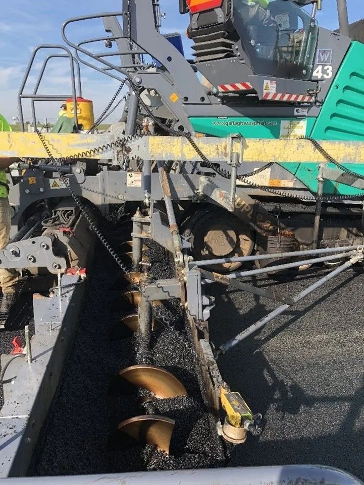
The head of material in the auger chamber is directly affected by the operation of the slat conveyors and augers on each side of the paver. When the slat conveyors and augers are operating, the mix is pulled from the paver hopper, through the tunnel, and is distributed across the front of the screed by the augers. If the flow of material and paver speed is relatively constant, the head of material pushing against the screed remains relatively constant as well, and the mat being placed has a smooth and consistent texture (see Figure 96).
Source: Asphalt Institute
Figure 96. Paving Wide with a Uniform Head of Material
If the head of material is allowed to vary, the screed moves up and down in reaction to the forces acting on it. When the amount of mix being carried by the augers is decreased because the slat conveyor and auger systems are running low or shut off, the screed moves downward, thus reducing the thickness of the mat behind the screed. As the slat conveyor and auger systems come on, more mix is carried back to the augers and across the front of the screed. This increases the force on the screed and causes it to rise to a new elevation, resulting in a thicker mat. Thus, it is very important to regulate the amount of mix in front of the screed since a consistent head of material in front of the screed is associated with a consistently smooth mat behind the paver.
7.3.3.4 Mixture Stiffness
Another factor that affects the balance of forces on the screed is the temperature or consistency of the mix. If a cold load of material is deposited in the paver hopper, the stiffer mix increases the force acting on the screed and causes the screed to rise, increasing the thickness of the layer placed. If, on the other hand, a hot load of mix is delivered to the paver, the decrease in viscosity of the binder material reduces the stiffness of the mix and reduces the force exerted on the screed. This situation causes the screed to fall and reduces the layer thickness. The mixture type can also play a role in the amount of force exerted by the head of material against the screed. For example, a coarse mix with a highly modified asphalt binder is stiffer than a sandy mixture with an unmodified binder.
7.3.4 Thickness Controls
Watch Video
As noted earlier, the screed is attached to the leveling or tow arms on each side of the paver through pivot points. The thickness control mechanism, usually either a crank or a handle, allows the screed to be moved or rotated around a pivot point. The key to the leveling action of the screed is the attachment to the tractor unit at tow points that pivot. This allows the screed to react to the forces exerted on it and remain in an equilibrium position. As the mix passes under the screed plate, the screed floats through the mix, establishing the mat thickness and the texture of the surface while providing the initial compaction of the mat.
The key to the leveling action of the screed is the attachment to the tractor unit at two points that pivot. This allows the screed to react to the forces exerted on it and remain in an equilibrium position.
7.3.4.1 Changing the Thickness Control Screws
For a constant position of the tow points (the tractor unit running on a level surface and without automatic screed controls), altering the setting of the thickness control screws changes the angle of attack of the screed and the forces acting on the screed. This in turn causes the screed to move up or down to a new elevation as the paver moves forward, thus altering the thickness of the mat being placed. The reaction of the screed to changes in the angle of attack is not instantaneous. There is a lag in the reaction that allows the screed to average out variations in the input forces acting on it.
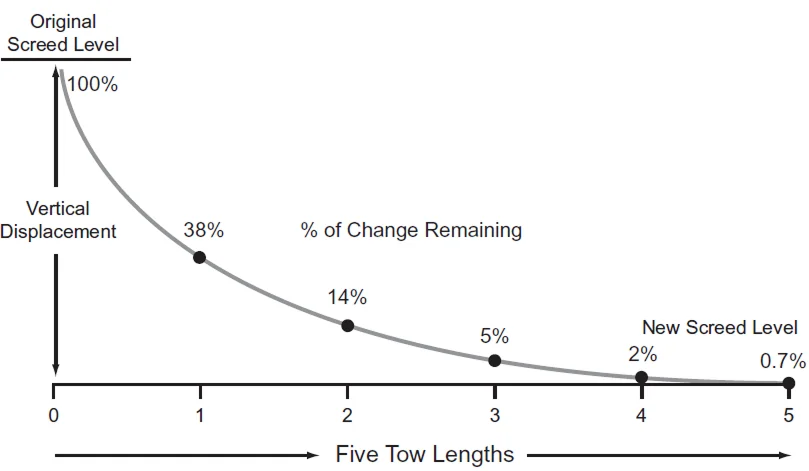
Figure 97 shows the reaction time of the screed when a change is made to the angle of attack, either at the screed or at the tow points. It takes approximately five times the length of the tow arms for the screed to complete 99 percent of the change, up or down, to the desired new elevation. This means that if the length of the tow arms is 10 ft (3 m), the paver must move forward at least 50 ft (15 m) before a thickness-control screw change is completely carried out by the paver screed. The same applies if the angle of attack of the screed is changed by the automatic screed controls changing the height of the tow points.
Source: Asphalt Institute
Figure 97. Distance Required for the Screed to Reach Equilibrium
It is essential for the screed operator to be aware of this lag in the reaction time of the screed. If a second change in the setting of the thickness control crank is made before the first change has been accomplished, the first change will never be completed, and it will still take an additional five times the length of the leveling arm for the second thickness change to be carried out. For this reason, continual changes in the setting of the thickness control devices are likely to be highly detrimental to the pavement smoothness.
Because of the delayed reaction time of the screed, a single mat-depth measurement should not be used to justify a change in the angle of attack of the screed. Indeed, even two or three measurements should not be averaged to determine whether a change in the setting of the thickness control cranks is needed. If the uncompacted thickness of the mat is to be checked using a depth gauge, the mat thickness behind the screed should be measured at least five times at 6-ft (2-m) intervals longitudinally. A better way to periodically check yield is to determine the distance 10 truckloads of mix should cover, based on the width and uncompacted thickness being laid. This distance is then compared with the length of pavement the paver has actually placed using the same number of tons of mix. If the distance covered is significantly different than it should have been, the setting of the thickness control cranks should be changed to slightly adjust the angle of attack of the screed to achieve the desired result.
Continual changes in the setting of the thickness control devices are likely to be highly detrimental to the pavement smoothness.
7.3.4.2 Changing the Tow Point Elevation
The above discussion also applies when there is a change in the height of the tow points on the tractor unit. If the height of the tow points moves, the change in their elevation translates to a change in the angle of attack of the paver screed. The paver must still move forward for approximately five times the length of the leveling arm on the machine for the screed to react to the change in the location of the tow points and move up or down to the new elevation. As a roadway is being paved without the use of automatic grade and slope controls, the tractor unit moves upward and downward in response to the grade of the underlying pavement. The vertical movement of the tractor translates into vertical movement of the tow points on the sides of the paver. Each time the tractor goes over a hump or into a dip in the existing pavement surface, the elevation of the tow points changes. This in turn alters the angle of attack of the screed, causing the amount of material flowing under the screed to be decreased or increased. The fact that it takes five times the length of the leveling arm before the screed reacts completely to a change in the location of the tow points allows the screed to reduce the thickness of the asphalt mix being placed over the high places in the existing surface and to place more mix in the low spots of the roadway. It is this averaging or leveling action that forms the basis for the floating screed principle discussed earlier.
The use of automatic paver controls, discussed in the next section, allows the paver to construct a smoother pavement by keeping the location of the screed tow points constant, relative to a predetermined reference, as the tractor unit moves up and down vertically in response to small changes in the grade of the underlying pavement surface. By maintaining the tow points at a constant relationship to the predetermined reference while the tractor moves vertically, the force on the screed remains constant, and the angle of attack of the screed is consistent in comparison with the reference. This allows the screed to carry out the leveling action needed over a longer reference length to reduce the roughness of the existing surface through the application of the new asphalt layer.
7.3.5 Screed Strike-Offs
The screed on some pavers is equipped with a plate on its front edge called a strike-off (or sometimes a prestrike-off). The purpose of this device is to control the amount of mix allowed to pass under the nose of the screed, thereby affecting the screed’s angle of attack. The strike-off is also used to reduce the wear on the leading edge of the screed.
When a strike-off is present, its position is important. If the strike-off is set too high, extra material is fed under the screed, causing the screed to rise. The resulting increase in the mat thickness must be overcome by manually reducing the angle of attack of the screed using the thickness-control cranks. This in turn causes the screed to pivot around its pivot points and ride with a lower angle of attack. Rapid wear of the screed nose plate results because the front portion of the screed is doing most of the compacting and finishing. This often leads to inconsistent mat texture. In addition, the screed settles more when the paver is stopped between truckloads of mix because the screed’s weight is carried only on its front.
When the strike-off is set too low, the thickness of the lift is reduced because not enough mix is allowed to pass under the screed. To maintain the proper mat thickness, the angle of attack of the screed must be altered, causing the screed to ride on its tail in a slight nose-up attitude. This increases the wear on the back edge of the screed and reduces the compactive effort applied by the screed. It also causes the screed to settle more whenever the paver is stopped because of the concentration of the screed’s weight on a smaller surface area.
The exact location of the strike-off depends on the make and model of paver being used and the thickness being placed. For relatively thin layers of pavement (1 inch [25 mm] thick or less), the strike-off is usually placed lower than when thicker lifts of mix are being placed. Similarly, for thick lifts of asphalt pavement (greater than 2 inches [50 mm]), the strike-off assembly is usually raised slightly above the normal position. In general, the strike-off is located in the range of 3/16 to 1/2 inch (5 to 13 mm) above the bottom plane of the main screed plate. No compaction of the mix occurs under the strike-off.
7.3.6 Vibratory Screeds
The amount of compaction imparted to the asphalt mix by the screed is a function of many variables. The properties of the mix itself are important—its stiffness, its temperature, and the amount of asphalt binder and moisture it contains all affect the ability of the screed to densify the mix. The degree of compaction achieved is also affected by the amount of bearing pressure applied to the mix by the screed, as well as the thickness of the mat passing under the screed.
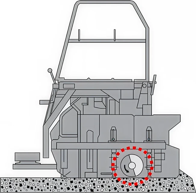
Screed vibration is achieved using a rotating shaft and counterweight. Two elements of the vibrating screed (see Figure 98) contribute to the degree of compaction achieved: the frequency of vibration (number of vibrations per minute) and the amplitude (amount of force) imparted by the screed. Increasing the revolutions per minute of the shaft will increase the frequency of the vibration and the compactive effort. Typically, the vibrators should be used at the highest frequency setting to obtain the maximum compactive effort.
The applied amplitude is determined by the location of the eccentric weights on the shaft. The position of the eccentric weights can be altered to increase or decrease the amount of compactive effort applied. Typically, the amplitude setting selected is related to the thickness of the mat being placed—lower amplitude for thinner lifts and higher amplitude for thicker lifts.
Vibrators should be used at the highest frequency setting to obtain the maximum compactive effort.
The density achieved by the paver screed is also a function of the speed of the paver. As the paver moves faster, the screed dwells for less time over any given point in the new mat, and the amount of compactive effort applied by the screed decreases. It can be expected that approximately 70 to 90 percent of the theoretical maximum density (TMD) of the HMA will be obtained when the mix passes out from under the paver screed.
Source: Asphalt Institute
Figure 98. Vibrating Screed
7.3.7 Tamper Bars
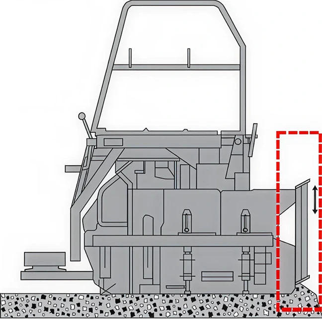
Some screeds have vertical tamper bars at their leading edge (see Figure 99) that serve a dual purpose: they strike off the mixture and direct the mix under the screed. This can often produce a greater initial density than a vibratory screed.
At higher paving speeds, the tamper-bar system does not have enough time to tuck the material under the screed. The speed at which this becomes an issue varies depending on mix properties and lift thickness. This can result in a surface texture where the surface aggregates appear to be dragging along behind the screed or even a torn asphalt pavement surface. Some pavers have screeds with dual tamper bars—a second line of tamper bars behind the first. While a second tamper bar may add additional initial density and allow for faster paving speeds, it makes the screed mechanically more complicated and harder to maintain.
To operate properly, tamping bars must be adjusted and maintained according to the manufacturer’s recommendations. Tamper bars typically protrude below the leading edge of the screed just enough to catch a fingernail on it, or 1/64–1/32 inch (0.4–0.8 mm). An agency-approved release agent should be applied at the end of each shift to keep bars from seizing up at the start of the next paving cycle.
Source: Asphalt Institute
Figure 99. Tamping Bar Screed
7.3.8 Screed Heaters
The screed is equipped with two or more heaters, or burners, depending on the age and model of the paver. The purpose of the heaters is to preheat the plate on the bottom of the screed to the temperature of the mix being laid. The screed should be heated before paving operations begin and at any time the screed has been raised out of the mix for an extended period. The screed should be at nearly the same temperature as the asphalt material passing under it to ensure that the mix does not stick to the screed plate and tear, imparting a rough texture to the mat. A properly heated screed provides for a more uniform mat surface texture and a more consistent mat thickness. To preheat the screed, the heaters are normally operated for a period of 10 to 20 min before the laydown operation begins. Care should be taken to avoid overheating, which can cause permanent warping of the screed plate. Electric screed heaters tend to provide more uniform heating of the screed. Usually within 10 minutes after paving has begun, the temperature of the screed plate has increased to the point at which it can generally be maintained by the temperature of the mix passing under it. Thus, the heaters are not needed and are shut off. A major misconception is that the heaters can be used to heat up cold material as it passes under the screed. This is simply not true. Only the very top surface of the mix is warmed up slightly, while the bottom of the screed may be superheated to the point of warping. For the same reasons, the screed heaters should not be used to increase the temperature of the mix sitting under the screed for a period of time while awaiting the arrival of the next haul truck.
A major misconception is that the heaters can be used to heat up cold material as it passes under the screed.
7.3.9 Screed Crown
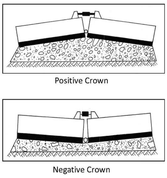
When paving crown into the pavement cross section (such as the centerline of the pavement), the screed can be angled at its center to provide the correct slope (see Figure 100). The amount of crown that can be introduced into the screed varies with the width of the screed and with the make and model of the equipment.
The crown is typically adjusted using a turnbuckle device to flex the bottom of the screed and impart the desired degree of crown. When rigid extensions are used, the cross-sectional profile of the mat can be altered at any of the points where the extensions are joined (such as when paving a different shoulder slope). If a hydraulically extendable screed is being used with the paver, the crown can be introduced not only in the center of the screed, but also at the points between the screed and the hydraulic extensions.
Source: Asphalt Institute
Figure 100. Screed Crown
When paving flat sections (one lane at a time), some paver manufacturers recommend that the screed be warped slightly, from front to back in its center, to facilitate the passage of mix under the screed and to obtain a more uniform texture on the asphalt mat. This process involves setting the lead crown on the screed slightly above the tail crown on the screed. In general, there should be more lead than tail crown, but the amount of difference depends on the make of paver and the type of screed. Normally the lead crown setting is 1/32 to 3/16 inches (1 to 5 mm) greater than the tail crown setting, with 1/8 inches (3 mm) being the average difference between the crown settings. For hydraulically extendable screeds, some paver manufacturers do not recommend setting any amount of lead crown into the front edge of the screed.
Because of different recommendations for different makes and models of pavers, it is suggested that the manufacturer’s operation manual be consulted before the crown is set into the screed.
7.4 Grade Control
The goal of the grade control system is to maintain the screed tow points on a smooth line of pull as the paver travels forward. The self-leveling action of the screed takes place continuously as the tractor unit travels over the roadway. The thickness of the asphalt mat being placed is determined by the reaction of the screed to the location of the tow points, the speed of the tractor, and the head of material in the auger chamber. The entire operation occurs without the thickness-control cranks on the screed ever being changed.
7.4.1 Manual Grade Control
It is easy to visualize that if a paver were a single axle unit with the tow points fixed to the axle, the tow point elevation would directly follow the existing surface, with minimal improvement to the final surface smoothness. Because pavers have multiple axles, with the tow points being roughly in the middle of the paver’s wheelbase, the length of the paver wheelbase becomes the reference. Thus, based on the combination of the tow point movement being the average of the wheelbase and the delayed screed reaction, under manual screed control the screed will average out deviations in the roughness by placing more mix over the low points and less mix over the high points of the existing surface.
7.4.2 Automatic Grade Control
Automatic grade controls enable the tow point to refer to a reference system that is not directly tied to the movement of the tractor unit but to a reference line established by a mobile ski, preset stringline, or remote (three-dimensional [3-D]) control. Automatic grade controls adjust the tow points up or down to maintain a constant height difference between the tow point and the reference line. Keeping the elevation of the tow points constant in direct relationship to the reference permits the screed to maintain a more consistent angle of attack, which in turn provides for a smoother mat behind the screed.
Many factors affect the smoothness of the mix placed by the paver. The use of automatic screed controls by itself does not ensure that the mat constructed will be smooth. Proper attention to the operation of the paver, as discussed in Section 7.3, is extremely important to obtaining a smooth-riding pavement layer. In addition, it is important to remember that because the free-floating screed places more mix in low spots and less mix on high spots, differential compaction of the asphalt mix will result in a compacted surface that is rougher than the surface placed.
It is important to remember that because the free-floating screed places more mix in low spots and less mix on high spots, differential compaction of the asphalt mix will result in a compacted surface that is rougher than the surface placed.
7.4.2.1 Mobile References
There are several types of mobile references (sometimes referred to as a “ski”). The purpose of a mobile reference system is to average the effects of grade changes in an existing surface over a greater distance than that obtained from just the wheelbase of the paver.
7.4.2.2 Floating-Beam Grade Reference
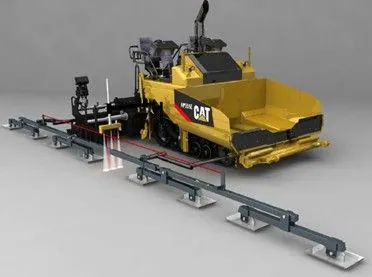
A floating-beam mobile reference is the most common grade reference system (see Figure 101). It consists of a rigid beam with a series of spring-loaded feet attached to the bottom of the beam. One or more of the feet can move over a single high or low point on the pavement surface without altering the overall slope of the beam along its length. The hinged “feet” can “walk” over small undulations or loose rock on the roadway without altering the slope of the beam. The floating-beam reference system will average the variation of the existing grade over 30–40 ft (9–12 m).
Source: Caterpillar Inc.
Figure 101. Floating-Beam Grade Reference
7.4.2.3 Sonic-Tracker Grade Reference
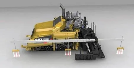
A sonic-tracker mobile reference system attaches a rigid beam to the side of the paver that holds multiple sonic sensors along its length (see Figure 102). The sensors direct sonic waves downward that echo off the surface. The echo is timed to establish the height of the sensor above the reference surface. The multiple height readings are continuously averaged together to provide a reference line.
Source: Caterpillar Inc.
Figure 102. Sonic-Tracker Grade Reference
7.4.2.4 Combination Grade References
The longer the grade reference used, the better the paver will average out variations in the existing pavement surface. Consequently, the smoothest pavements are built using a combination over-the-screed mobile reference system that senses off the existing grade in front of the paver and reaches over-the-screed to sense off the new mat being placed behind the screed (see Figure 103). Since the new mat is significantly smoother than the existing pavement surface, the majority of the variations detected are limited to those measured by the front sensor(s). Combination systems can be made up of individual floating beams connected by either a rigid framework or spring-loaded wire stretched over the screed. This type of system can reach between 40 and 60 ft (12 to 18 m) in length.
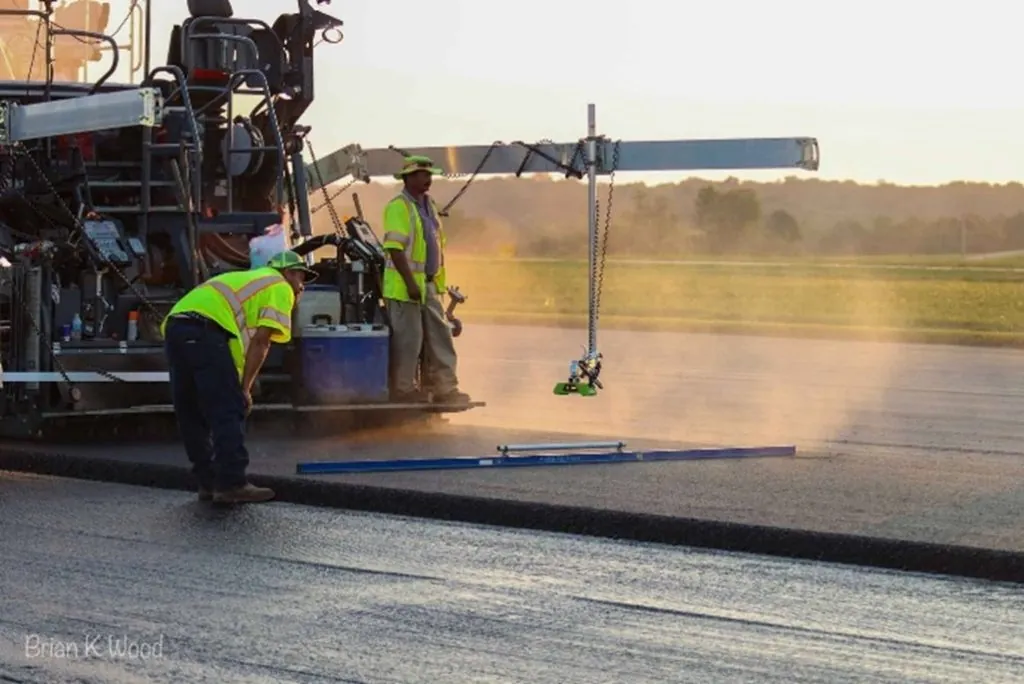
Source: Brian K. Wood
Figure 103. Over-the-Screed Grade Sensor and Cross-Slope Checking
7.4.2.5 Fixed-Grade References
A fixed-grade reference refers to a method of grade reference that duplicates an existing surface or profile-primarily a single point reference (matching shoe or non-contact sensor) or a fixed stringline reference. The purpose is to duplicate or mirror the respective reference.
7.4.2.6 Single-Point Reference (Matching Shoe)
surface, such as an adjoining lane, curb and gutter, or a lower surface layer. A single-point reference device may be a matching shoe or a single non-contact grade sensor.
Fixed-grade references using a single device should be used with caution because anomalies, such as mix spillage and pebbles or drainage inlets in curb and gutter, can create an irregular profile that will be directly reflected in the adjacent paving surface.
Fixed-grade references using a single device should be used with caution because anomalies, such as mix spillage and pebbles or drainage inlets in curb and gutter, can create an irregular profile that will be directly reflected in the adjacent paving surface.
The location where the single-point sensor is placed on the paver will impact the response of the paver to grade changes. It is important to remember that the sensor is calibrated to detect a specified reference or measure a distance. As a wand or matching shoe traverses a reference, the tow point will maintain a constant distance to within a very small tolerance. A non-contact sensor is constantly measuring a distance, and the tow point moves to stay within a very close tolerance to a predetermined distance. Both types of sensors, shown in Figure 104, will continuously call for the tow points to change until the offset with the sensor returns to its “comfort range.”
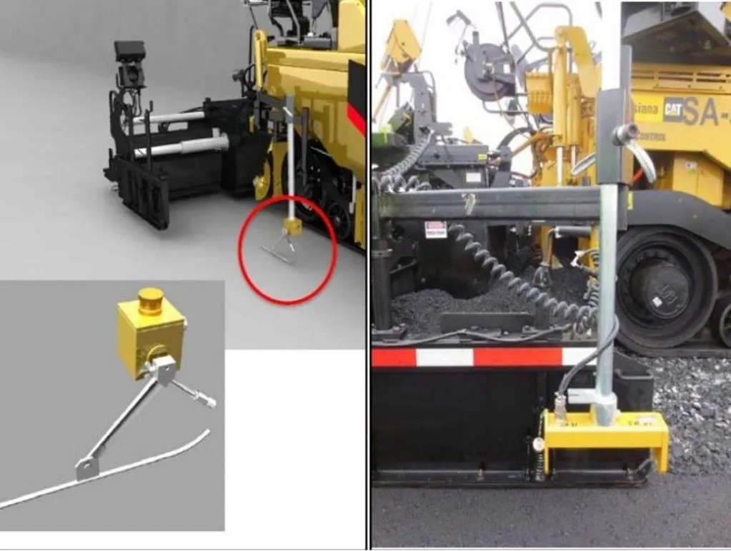
Source: Caterpillar, Inc.
Figure 104. Single Point Grade Referencing
Placement near the tow point locks in the distance between the grade reference and the tow point elevation. The sensor and tow point really do not care what the screed does as it trails one tow arm length behind the tow point. The fact that it takes the screed one tow arm length to get 65 percent of the angle of attack change reconciled will put the screed very close to where it should be as paving progresses. Placement of the single-point sensor at the tow point will result in smaller movements of the tow point and smoother pavement, but it may not always match the grade reference exactly.
When the sensor is placed at the rear of the tow arm, near the auger, the tow point reaction is quite different. When the sensor is mounted near the auger or screed, the sensor more closely follows the position of the screed. When the sensor gets out of its comfort range, it calls for an adjustment to the tow point elevation. But since the screed is slow to react to the tow point change, the sensor continues to call for more movement of the tow point; hence the tow point continues to move until the sensor is satisfied. These movements of the tow point height are larger and more rapid when compared to the tow point reaction with the sensor located at the tow point. The result is that the screed quickly reaches the new elevation called for by the sensor. Placement of a single point sensor near the auger will obtain the closest continuous match to the grade reference, but smoothness may be reduced.
When placing the second lane of a base course or a binder course layer, it may be better to use a longer mobile reference ski instead of a joint-matching shoe. The mobile reference will provide better input for constructing a smooth pavement surface than a single-point sensor. If sufficient smoothness has been achieved in lower layers, a single-point matching device would be an appropriate choice to match adjacent surfaces or specific elevation for the final lift.
7.4.2.7 Fixed Stringline
The use of an erected stringline, shown in Figure 105, provides the opportunity for the placement of the smoothest possible asphalt mat behind the paver screed. The stringline can be made of wire or nylon cord. This method of supplying elevation input provides the most consistent reference for the paver tow points, enabling a predetermined grade to be matched very accurately if the controls are used properly.
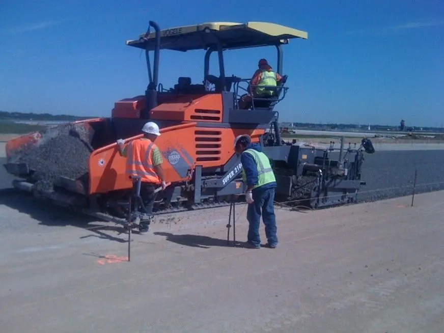
Source: Applied Research Associates, Inc. (ARA)
Figure 105. Stringline on an Airfield Project
Unfortunately, there are several obstacles to successful implementation of fixed stringline control. The most notable are that it is very expensive and time-consuming to install and maintain. In addition, the line must be kept very taut and undisturbed by personnel and equipment over long sections of the project. Thus, for the vast majority of highway paving projects, an erected stringline is not used.
However, fixed stringlines can be very helpful where longitudinal and transverse profiles along with final elevation points are important, such as airfields. Special projects such as racetracks or other applications with critical superelevated curves may be good candidates for fixed stringline grade references.
It is important to note that establishing a smooth paving platform contributes significantly to a uniform and balanced laydown operation. Using automatic controls on milling machines improves mixture yield, smoothness, and in-place density.
7.4.3 Slope Control
Paving that is done with automatic screed controls as described in Section 7.4.2 is often accomplished with a combination of grade control on one side of the paver and slope control to determine the grade on the other side of the machine. The slope control operates through a slope sensor that is located on a cross beam between the two side arms of the screed. The cross slope is regulated by a pendulum device that is part of the slope control system. The required degree of cross slope is simply dialed in to the slope controller, shown in Figure 106.

Source: Asphalt Institute
Figure 106. A Modern Cross Slope Controller
One side of the screed is controlled by the grade sensor(s), while the other is controlled by the slope controller. In almost every case, the inside or centerline edge of the finished mat is controlled by grade and the outside edge by slope. It is very difficult to match the centerline joint if slope control is used to control the inside edge of a paved lane. It is extremely difficult, if not impossible, on multiple-lane sections.
When slope control is used, the thickness of the mat on the side of the machine that is controlled by the slope sensor may be variable in depth, depending on the condition of the existing surface. Without regard to the condition of the existing surface, the slope controller maintains a constant cross slope of the finished mat exiting the paver, regardless of the resulting thickness of the asphalt layer placed. If there is a high point in the present pavement surface, the slope controller causes the screed to place less material over that location; if there is a low point in the existing pavement, the slope controller causes the screed to deposit more mix in that location. It is good practice to check the slope of the lane routinely with a carpenter level or other method.
When properly operated, a slope controller will very accurately place a lift with a surface at the exact slope. However, if the sublayer is irregular, differential compaction will result, and the final surface will not be uniform across the section after rolldown. A properly prepared or corrected base layer that conforms to the longitudinal and transverse profile will greatly enhance a uniform and balanced paving operation. For a wide pavement, such as an airport runway, it is good practice to continually check the elevation of the outside edge of the mix being placed. While the use of one or more stringlines across a wide pavement can help provide the proper cross slope, dual mobile reference skis (controlling both sides of the paver) are often utilized.
7.4.4 Remote Grade and Slope Control (3-D Paving)
Traditional grade and slope control is often referred to as two-dimensional (2-D) paving. Three-dimensional (3-D) paving allows a laydown operation to achieve a specific elevation while maintaining longitudinal grade and slope. Achieving an exact result requires control of the lower layers of the pavement section. Since the placement of nonuniform mat thickness results in differential rolldown, a successful project begins with a precise base layer placement or milling operation.
3-D paving is a process where the tow points of the paver are automatically controlled by an electronic file that contains all the grade, slope, and elevation data. This data can be from the original project design file or captured and recorded during project construction, for example, during subgrade preparation, base layer placement, or milling operations.
3-D paving begins with one or two prisms located on the screed, shown in Figure 107. These prisms are mounted at a fixed and measured height above the screed. The prisms are constantly tracked by an onsite universal total station.
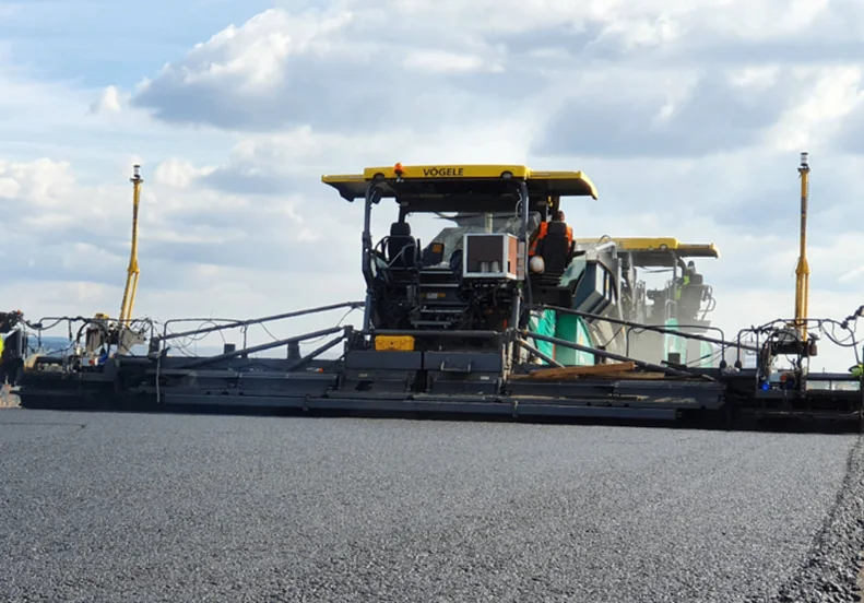
Source: SITECH Construction Systems
Figure 107. Dual Receivers on a Paver
Depending on the project site, there may be multiple total stations because they must maintain line of sight with the paver and are limited in range to 500–1000 ft (150–300 m), depending on the system provider. Total stations (shown in Figure 108) constantly measure the location of the paver prism and transmit position data to a receiver and controller unit on the paver. The controller processes the position data received and controls the tow point height to maintain the screed at the final elevations in the data file.
Some systems, often called 3-D grade control, may use only one prism to control the grade line (replacing the ski) on one side of the screed, with the other end of the screed controlled by the slope controller or matching shoe. Other systems use two prisms, one on each side of the screed, to provide full 3-D control.
Total stations are located at control points throughout the project, with known coordinates and elevations pre-determined for each. 3-D paving is typically used on strategic projects with a limited footprint due to the limited range of the total stations. Excellent results can be expected on all types of projects but may become difficult to execute on long, high-tonnage overlay projects, whereas airfield projects are excellent candidates for 3-D paving.
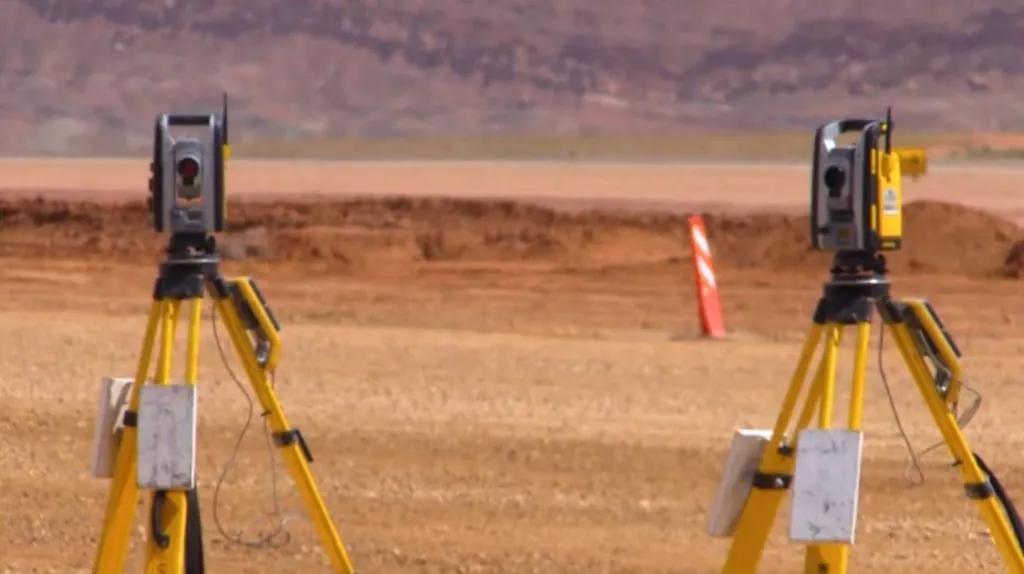
Source: JP Excavating, Inc.
Figure 108. Universal Total Station Tracking Paver
7.5 Layer Thickness
Watch Video
After asphalt material is spread and struck off by the screed, it is in a “loose” state even though it has received some initial compaction from the tamper bar or vibratory screed. It is critical that the thickness of the loose mixture after it has been placed is sufficient to allow for consolidation through the compaction process so that the final thickness meets the thickness specified in the project plans.
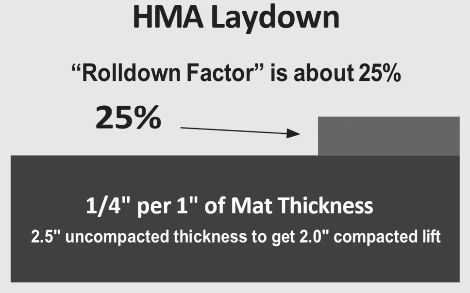
To accomplish this, a rolldown factor for each material must be considered. This factor varies depending on mixture type, with a common rolldown factor (for a typical dense-graded mix) being approximately 25 percent (see Figure 109). For instance, assuming a 25-percent rolldown factor on a 2-inch compacted lift thickness, the thickness placed by the paver must be 25 percent thicker or 2.5 inches thick. When gap and open-graded materials are being placed, a rolldown factor of about 15 percent is probably more accurate. During paving operations, it is a best practice for the screed operator to regularly measure the thickness of the loose mat directly behind the paver. When necessary, adjustments to mat thickness should be made to ensure that the proper amounts are being placed. A more in-depth discussion regarding the construction of transverse joints at startup is discussed in Chapter 9, Section 9.2.2.
Source: Asphalt Institute
Figure 109. Rule of Thumb Rolldown Factor for Dense-Graded Mixtures
Spread rate is a useful calculation that onsite inspectors and paving foremen can use to confirm the paver is set up properly and placing the proper amount of material. It is based on the unit weight information from the lab and is expressed in terms of pounds per square yard of material for every inch of compacted thickness. These units are typically expressed as lbs/yd2-inch.
The formula for spread rate is as follows:

With this factor, quantities can be readily calculated as follows in any number of terms based on the width, feet, and the depth and compacted inches for a given distance:
Tons/linear foot (T/LF), which is useful determining tonnage to move a paver a certain distance.
Tons/project station (T/sta) to compare quantities with the project plan sheets.
Tons/mile (T/MI) to compare with overall contract quantities.
7.6 Establishing Paver Speed
Planning is necessary for constructing a high-quality asphalt pavement, and it begins by coordinating the amount of material needed, the number of trucks needed, and the amount of compaction needed before the mix temperature falls below compactible levels. Uniform paver speed is essential to keep the paving plan intact. The paver operator must be trained to monitor the arrival rate of the material, the flow of material through the paver, and the pace of the compaction train and try to keep all three operations in balance. The paver operator’s main goal should be to maintain a pace consistent with the pace of the compaction train and not worry about surges of delivery trucks arriving in front of the paver. By releasing trucks from the paver in an orderly manner, the paver operator can help maintain spacing of trucks returning to the plant.
To balance a paving operation that provides continuous forward motion and uniform pavement placement, calculations must be made to estimate the following:
The number of trucks needed to deliver mix.
The paving speed.
The production capacity of the compaction train.
A perfectly balanced mainline highway paving operation will run continuously, without interruption, at the same rate of production as the asphalt plant. The number of trucks required is covered in Section 6.2 and is assumed to be sufficient for continuous operation for the following example.
Calculating Paver Speed
Assumptions:
Plant production = 350 T/hr
Compacted unit weight = 150.2 lbs/ft3
Compacted lift thickness = 2.0 inches
Paving width = 14 ft
Determine the spread rate:

Or directly calculate tons per linear foot of mix:

1 ton of mix will cover:

The distance paved in 1 hour equals:

Calculate paving speed in feet per minute:
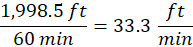
This calculation is a theoretical number that assumes continuous operations with no paver stops. If paver stops are anticipated, then they should be factored in via an efficiency factor. Maintaining the same production rate per hour will require the paver to move faster. If it is anticipated that the paver will be moving 90 percent of the time, this should be accounted for with an efficiency factor of 0.90, as shown below:
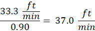
One can see that even if the paver is down 10 percent of the time, it does not take a large increase in ground speed to make up the lost time. If the compaction production rate (covered in Section 8.5.2) is not able to keep up with a calculated paving speed, the paver speed and plant production will need to be reduced or additional rollers added to maintain production and achieve the specified density.
7.7 Related Paving Operations
While asphalt pavers will place most of the mixture on a project, there will always be small, inaccessible areas where it is not practical or where pavers cannot maneuver to place the needed mixture.
7.7.1 Hand-Spreading Operations
Small repairs and patching, small drainage swales, variable-width areas such as narrow tapers, radii, fillets, etc., are examples of areas that require hand-spreading and finishing.
Attention to the process is required when placing and spreading by hand. The mixture should be delivered uniformly in small piles to avoid mix segregation, placing the supply piles in a manner where shovelers and rakers must move the bulk of material the least distance. Sufficient space should be available so that workers are not required to stand in the fresh mix. Broadcasting or throwing mixture from shovels should never be allowed because segregation will result. The small piles should be spread using shovels and rakes/lutes, discarding any clumps of mixture that have formed into lumps and do not break down easily when struck with a shovel edge. After uniformly placing the mix, and before rolling starts, the surface should be checked with a straightedge and all irregularities corrected. On cool days, careful attention should be paid to the mix temperature. Hand placement of mix accelerates the cooling of the material, and compaction needs to begin as soon as possible to ensure adequate time for compaction.
It is important to understand that hand-spread mix has not been pre-consolidated by a vibrating screed or tamping bar, and the rolldown factor of the mixture may be significantly greater than mix placed by a paver. Thirty to 50 percent rolldown is not uncommon with hand-placed material.
7.7.2 Supplemental Operations and Appurtenances
Items considered supplemental paving operations include roadway widening, shoulders, and superelevated curves. In some cases, such as widening and shoulder construction, specially designed pieces of paving equipment and attachments are available to perform the work easily and efficiently. Certain other roadway appurtenances, such as asphalt curbs, dikes, ditches, spillways, and slopes, are increasingly becoming part of paving contracts. For these jobs, special equipment or special asphalt mixtures (or both) may be required.
7.7.3 Roadway Widening and Shoulders
Typical two-lane pavements are 24–28 ft (7.3–7.9 m) wide. Many thousands of miles of primary routes are inadequate in width and thickness to meet today’s standards. For details on geometric standards, refer to “A Policy on Geometric Design of Highways and Streets, 7th Edition, 2018,” commonly referred to as the “Green Book,” from AASHTO for more information.
For safety reasons, evaluating and planning can greatly improve the original alignment of substandard roadways that need widening before strengthening them with overlays. Widening may range from a few feet (greater than 1 m) on one side of a pavement to the addition of full-width traffic lanes on both sides. For safety reasons, proper traffic control must be maintained throughout construction. Work should never take place on both sides of the pavement at the same time and should avoid excessive lengths of open trench. Widening requires trenching to adequate width and depth, typically by templates or attachments to a motor grader so that the walls and base are neat and true to line and grade. For wider excavations, a continuous excavator or a milling machine that loads trucks while cutting the trench to appropriate line and grade can expedite the process. Contractors should roll the subgrade with adequate compaction equipment until it is firm and free of loose material and compaction exceeds the minimum requirements. Typical compaction references are a Modified Proctor Test or a California Bearing Ratio Test to confirm compliance with the required density. Workers should trim and clean the existing pavement edges nearly vertically and remove all dirt and foreign material, then spray the edge with an ample amount of tack coat to adhere the new mixture to the existing pavement. They should then place the asphalt pavement base in layers and compact it to the required density. Appropriate compaction equipment will need to be selected—vibrating plates for narrow trenches, special trench rollers available in different widths, or full-size rollers for wider sections.
When adding shoulders to an existing roadway, contractors should observe the same procedures and precautions used for roadway widening. For safety reasons, it is important that enough mix is placed to assure that after rolldown, the new shoulder height matches the existing pavement edge to avoid drop-offs or ponding water.
When paved shoulders are part of the initial construction, contractors should use the procedures for mainline paving. Variable-width screeds should be considered to pave shoulders at the same time as the mainline and eliminate the longitudinal edge joint.
7.7.4 Superelevation
On new construction, paving curve sections with superelevated cross slopes is generally not a problem. The prepared base and/or foundation material is usually superelevated or sloped the same as the new pavement. This allows placing the same uniform thickness on the curved or superelevated sections as on the tangent or straight sections. As the paver proceeds through the transition to the superelevated section and out again, the paver and the screed tilt accordingly on the prepared foundation, and little, if any, adjustment in the screed controls is required.
When building a superelevated pavement on a flat or crowned base or subgrade, use variable thickness layers to build the pavement. Pavers equipped with automatic slope controls allow the transverse cross slope to be “dialed in” as the paver moves through the superelevated curve. Sensors riding on an erected or traveling stringline maintain grade control for the screed nearest the sensor. The depth at the other side depends on the transverse cross-slope setting.
When the paver reaches the point where the slope begins to change and transitions into a superelevated section, stakes or other markers on adjacent lanes indicate the required cross slopes for the screed operator to dial in/out continuously as the paver proceeds through the transition. The change in cross slope is gradual, and small errors in dialing will not affect the riding quality of the pavement. Once the paver enters full superelevated cross slope, the slope setting will remain the same throughout. Then, as the paver exits the fully superelevated section, the cross slope is gradually dialed out using the same procedure, but in reverse.
7.8 Best Practices Checklists
The following list includes important points to keep in mind for the paving foreman, superintendent, or inspector.
7.8.1 General Guidelines
- Never run the hopper empty between loads. (The level of material in the hopper should not be allowed to fall below the top of the tunnel opening.)
- Establish and maintain a continuous paving speed. (Establish the speed by balancing the delivery of material with the compaction process.)
- Control the head of material in the auger area to within ±1 inch (±25 mm).
- Do not allow trucks to bump into the paver.
- Do not spill material on the grade in front of the paver (when dumping directly into the paver hopper or cleaning truck tailgates).
- Do not fold the hopper wings between loads. It is best to only fold the wings when cleaning out the hopper, either at the end of a shift or due to an extended work stoppage.
- Practice good paver starting and stopping techniques.
- Eliminate overcorrecting of the depth screws.
- Make sure the end gates are adjusted properly and in contact with the existing pavement.
- Use best practices for compaction of the in-place asphalt pavement and ensure that all roller marks are smoothed out (see Chapter 9).
7.8.2 Establishing and Maintaining Proper Head of Material
- Set the flow gates and/or slat conveyors to maintain a continuous auger speed.
- Make sure the material feed sensors are operating properly.
- Install tunnel extensions so they are within 12 to 18 inches of the endplate.
- Lower the auger to a position approximately 2 to 4 inches above the screed plate.
- Position, heat, and null out the screed properly on the starting blocks.
- Charge the auger chamber with material, allowing the augers to turn until the auger chamber is filled to the height of the auger shaft, out to the end gate. They stop automatically. (Use a shovel if necessary to fill any void at the outside near the endplate.)
- Begin paving, making head of material adjustments to match the paving width, depth, and paving speed while maintaining a consistent head of material at the augers.
7.8.3 Reducing Segregation in the Paver Hopper
- Observe arriving haul units to verify proper loading procedures are being followed.
- Minimize spillage in front of the paver.
- Do not allow the level of material in the hopper to fall below the top of the tunnel opening.
- Properly fold in the hopper wings only when necessary.
- After paving stops:
- Move paver to a designated cleanout area.
- Fold hopper wings to facilitate cleaning hopper.
- Transport cold or segregated mixture from hopper wings back to the plant for recycling.
7.8.4 Reducing Mat Texture Imperfections
- Maintain equipment in good condition and make all needed repairs in a timely manner.
- Set augers at the proper height settings for the mix and lift thickness being placed.
- Adjust bolt-on and hydraulic screed extensions in a uniform plane.
- Check and adjust the lead and tail screed crown to ensure it meets the equipment manufacturer’s requirements.
- Ensure tunnel and screed extensions are in place and within 12 to 18 inches of the end plate.
- Establish and maintain a balanced paving speed and constant head of material.