

4.1 Introduction

Watch Video
The purpose of an asphalt mix plant is to blend aggregate and asphalt binder together at an elevated temperature to produce a homogeneous asphalt paving mixture.
Two basic types of HMA plants are currently in use: batch plants and continuous flow drum-mix plants.
Regardless of the type of production plant, the basic purpose is the same—to produce an asphalt mix within a specific temperature range containing the specified proportions of asphalt binder, aggregate, and any additional additives required. Both batch plants and drum-mix plants are designed to accomplish this purpose.
The following basic operations involved in producing asphalt mix are the same regardless of the plant type:
- Proper storage and handling of asphalt mixture components at the mixing facility.
- Accurate proportioning and feeding of the aggregate to the dryer.
- Effective drying and heating of the aggregate to the proper temperature.
- Efficient control and collection of the dust from the dryer.
- Proper proportioning, feeding, and mixing of asphalt binder and additives with heated aggregate.
- Correct storage, dispensing, weighing, and handling of finished mix.
The major difference between batch and drum-mix plants is in how they mix asphalt binder and aggregate after the aggregate has been proportioned, dried, and heated to the final mix temperature.
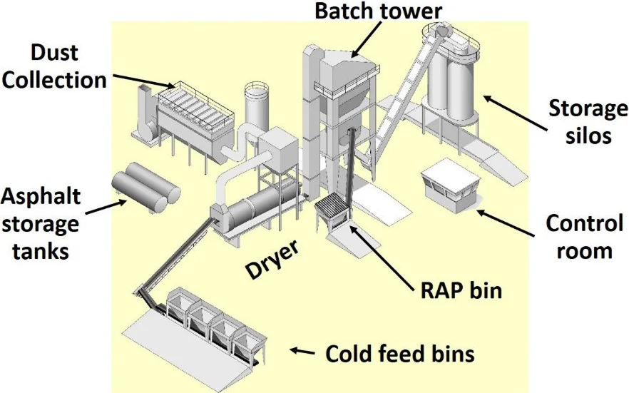
Batch plants screen and fractionate hot aggregate into separate bins after leaving the dryer. Asphalt binder and fractionated aggregate are then individually weighed into predetermined batches and mixed in a pugmill mixer, one batch at a time (see Figure 21).
Batch plants screen and fractionate hot aggregate into separate bins after leaving the dryer. Asphalt binder and fractionated aggregate are then individually weighed into predetermined batches and mixed in a pugmill mixer, one batch at a time.
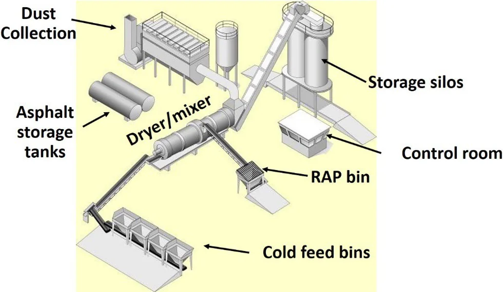
Drum-mix plantsdry the aggregate and blend it with asphalt binder in a continuous process within the dryer drum.
Source: Asphalt Institute
Figure 21. Batch Plant Components
Drum-mix plants dry the aggregate and blend it with asphalt binder in a continuous process within the dryer drum; hence the name drum mixer (see Figure 22).
Source: Asphalt Institute
Figure 22. Drum Mix Plant Components
Uniform and continuous operations are critical to the production of quality asphalt mix. Uniformity helps ensure the mix is consistently produced to meet project specifications. This includes uniform delivery of raw materials, uniform material proportioning, and continuous, uniform operation of all plant functions.
4.2 Material Storage and Handling
The quality of the asphalt mix produced is only as good as the material going into the plant. One of the necessities of ensuring quality production is that an adequate supply of suitable material be available prior to and during mixing operations. The following sections discuss the principles of handling and control of both asphalt binder and aggregate materials common to all asphalt mix plants.
4.2.1 Asphalt Binder
Asphalt binder is a black, thermoplastic, cementitious material whose consistency and viscosity changes based on temperature. When heated sufficiently it softens and becomes less viscous, allowing it to be pumped and to coat aggregate particles during asphalt mix production.
4.2.1.1 Binder Delivery
In most instances, asphalt binder comes from a pre-tested source and is accepted by certification. Records must be kept of all asphalt binder deliveries to the plant. The records should include the following information:
- Asphalt binder grade.
- Supplier’s name and location or shipping point.
- Plant and project identification (if dedicated to a particular project).
- Date of delivery.
- Delivery invoice number.
- Grade certification and Material Safety Data Sheet.
- Identification of any additives incorporated at the binder terminal.
- The specific gravity or unit weight per gallon at 60 °F (liters at 15 °C).
- Asphalt binder quantity by weight.
Similar records should be kept on all other materials (such as mineral filler, hydrated lime, or other additives that are incorporated into the mix).
4.2.1.2 Binder Storage
The asphalt binder supply system consists of two major components. The first comprises one or more tanks used to store the asphalt binder until it is needed by the mixing plant. The second is a pump and meter system used to draw asphalt binder from the storage tank.
Asphalt binder storage tanks are insulated and heated to maintain the correct temperature to assure the binder can be pumped and mixed with hot aggregate. Temperatures are typically maintained by thermostatically controlled electric heat or a hot oil coil system, which circulates hot oil through a series of coils inside the storage tank. The system maintains the proper temperature of the asphalt binder, generally in the range of 300 °F (150 °C) to 350 °F (180 °C), depending on the type of asphalt binder.
Tanks that store modified binders are often equipped with agitators or stirring paddles to maintain constant circulation. For short periods of time, circulation using the asphalt plant’s own pump(s) can be used for the same purpose. Some modified asphalt binders can have specific agitation requirements. Asphalt mix producers are encouraged to consult with the liquid binder supplier for proper temperature and storage requirements.
4.2.1.3 Binder Sampling
Asphalt binder samples are typically taken from a sampling valve in the delivery line between the binder storage tank and the plant after all inline binder additives have been added. When no inline binder additives are used, samples may be taken from a sampling device on a delivery vehicle, discharge line, or storage tank.
Following are a few important rules to follow when sampling asphalt binder:
- Enlist only a competent, well-trained technician to perform sampling.
- Wear personal protective equipment (such as gloves, face shield, and long-sleeved shirt) to protect from burn hazards.
- Ensure samples are representative of the entire shipment by taking them from the sampling valves provided for that purpose.
- Follow sampling methods described in ASTM D140 and AASHTO T 40.
- Use only new, clean, and dry metal sample containers.
- Allow at least 1 gal (4 L) of asphalt binder to flow from the sample valve prior to obtaining a representative sample.
- Seal filled sample containers immediately with clean, dry, tight-fitting lids. Any spilled material should be wiped from the container with a clean, dry cloth—never with a cloth dipped or soaked in solvent.
- Label clearly all sample containers for sample identification. Container lids should also be labeled because once a lid is removed, it will be necessary to match it to the appropriate container. Tags should be used only when there is no danger of their being lost in transit.
When asphalt binder is delivered from a transport vehicle into a storage tank, it is important to ensure that either the tank is clean or that it does not contain material that will contaminate the binder being pumped into the tank. If it is empty at the time the new material is being added, the tank should be checked to ensure that no water has accumulated on the bottom. If asphalt binder is loaded on top of an asphalt emulsion or on top of a layer of water in the tank, violent foaming of the asphalt binder may occur, creating a serious safety problem.
When asphalt binder is delivered from a transport vehicle into a storage tank, it is important to ensure that either the tank is clean or that it does not contain material that will contaminate the binder being pumped into the tank.
It is important to be aware that some asphalt binder can remain in the bottom of an “empty” tank. Therefore, placing asphalt binder of one type or grade into a tank that previously contained a different type or grade can cause an alteration of the properties of the asphalt binder to the point that it no longer meets specifications.
Maintaining a good line of communication with the liquid binder supplier is a critical step in assuring proper temperature, storage, and safety procedures are established.
4.2.1.4 Binder and Mixture Temperatures
Both asphalt binder and aggregate must be heated before they are mixed—the binder to make it fluid enough to pump and properly coat the aggregate, and the aggregate to make it dry and hot enough to accept theasphalt binder and produce a well-coated mix at the desired temperature and free of moisture.
The temperature of the aggregate controls the temperature of the mixture. Normally, a mixing temperature is specified based on the characteristics of the asphalt binder and on factors relating to mixing, placement, and compacting conditions.
Mixing should be done at the lowest temperature that provides for complete drying and coating of the aggregate particles and produces a mixture with satisfactory workability. Binder and additive supplier mixing temperature recommendations should be used if possible. Two asphalt binders with the same PG could have different optimum mixing temperatures, especially if they are produced by different methods. And they most certainly will have different mixing temperatures if one binder is modified and the other is not, or if warm-mix additives are involved.
Mixing should be done at the lowest temperature that provides for complete drying and coating of the aggregate particles and produces a mixture with satisfactory workability.
The following procedure is recommended for selecting the starting point for plant mixing temperatures:
- Select plant mixing temperature based on recommendations from the binder supplier, previous experience with the same binder grade from this supplier, and project conditions (including weather and seasonal conditions, lift thickness, haul distance, and mixture considerations).
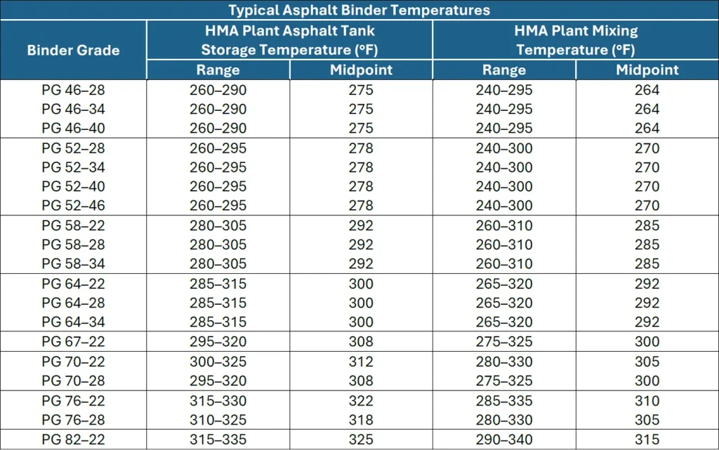
- In the absence of supplier guidance, consult Table 4 for recommended plant mixing temperature for a given binder grade.
- Generally, when using the table, use the middle of the range of temperatures as the starting point for the PG binder selected.
- Typically, plant mixing temperatures will range from 265 to 300 °F (130 to 150 °C) for standard dense-graded mixtures using neat (unmodified) binders.
- Do not allow plant mixing temperatures to exceed 350 °F (180 °C) to avoid excessive aging of the asphalt binder.
- Use caution in raising plant mixing temperatures too high to improve field laydown and compaction. Excessive temperatures can have the following negative consequences:
- The asphalt binder may be damaged.
- Unnecessary fumes and odors may be generated.
- Excessive asphalt binder draindown may occur in certain mix types.
- The mixture may be tender and unstable under compaction equipment.
- Unnecessary cost and emissions are added.
Table 4. Typical Plant Binder Storage and Mixing Temperatures
4.2.2 Aggregate
Stockpiling and handling techniques for aggregate materials are the same regardless of the plant type used. It is important to understand that individual aggregate stockpile characteristics—including quality and gradation—can only be achieved during aggregate production, not at the asphalt mixing facility.
4.2.2.1 Testing and Certification
Aggregate property data should be recorded as aggregates are received at the plant site. If the material has not been tested or material changes have occurred due to handling, sufficient random samples should be obtained and tested to ensure compliance with all specifications after aggregate transport is complete. At a minimum, tests should be made available for gradation (washed sieve analysis) for all aggregate materials. It is recommended that all aggregate properties specified in the contract or plans be performed or verified during aggregate production and delivery, as discussed in Chapter 3.
4.2.2.2 Storage and Handling
Aggregate must be handled and stored in a manner that avoids contamination, minimizes degradation, and prevents segregation. The stockpile area should be clean and stable to prevent contamination. Materials should be stockpiled on a free-draining grade to prevent accumulation of moisture.
Site planning is important when building stockpiles at plant locations. Controlling drainage onsite is necessary to prevent contamination of aggregate by front-end loaders charging the plant and haul trucks delivering material. Plant sites and aggregate storage areas in low-lying areas may require the construction of a well-drained working platform or site to assure aggregate material can be handled without adulteration.
At permanent plant sites, paving the stockpile area will help prevent subgrade contamination and expedite moisture drainage from the stockpiles. Storing aggregate stockpiles, especially RAP, under a roof is an increasingly cost-effective option to minimize excess moisture. A consistently low moisture content lowers heating and drying costs and increases plant productivity and mixture uniformity.
To prevent intermingling and cross contamination of different aggregates, stockpile areas must have enough space for clear separation of stockpiles or make use of bulkheads (vertical dividers) to maintain separation of the materials. When bulkheads are used, do not allow the stockpiles to overflow into adjacent aggregate material.
4.2.2.3 Stockpiling and Segregation
One of the primary concerns with the handling and stockpiling of aggregate is segregation. The method used to control segregation depends on the nature of the material. Aggregates that are well-graded, from the NMAS to the finest particles, are the most prone to segregation. Sand, crushed fine aggregate, or any single-size aggregate material can generally be handled and stockpiled with little, if any, segregation.
When a well-graded aggregate containing both coarse and fine particles is placed in a stockpile with sloping sides (a cone shape), segregation is sure to occur as the larger particles will roll down the slope. Stockpile segregation can be nearly eliminated by making use of multiple fractionated material piles. Building a stockpile in layers can also help minimize this type of segregation. Pushing or casting aggregate over the side of a stockpile will result in segregation. Equipment operating on the stockpile, especially steel-tracked, should be minimized to prevent aggregate breakage, fines generation, and degradation.
Stockpile segregation can be nearly eliminated by making use of multiple fractionated material piles.
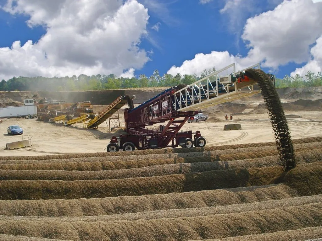
The use of radial stacking conveyors allows more material to be stockpiled over a smaller area by raising the elevation of the stockpile. Proper use of a radial stacker includes raising the conveyor slowly after moving it horizontally to cause the stockpile to grow vertically. Segregation can occur if a stacker is allowed to drop aggregate from an elevated height.
Figure 23 illustrates the capability of a telescoping radial stacking conveyor, which is very effective in eliminating stockpile segregation.
Source: Masaba, Inc.
Figure 23. Magnum Telescoping Conveyor Building a Stockpile in Windrows
4.2.3 Additives
Traditional asphalt mixtures consisting of only unmodified asphalt binder and virgin aggregate are becoming less common. Most modern asphalt mixtures contain modifiers or additives of some type. Recycled asphalt pavement and modified asphalt binder have been in use for many years and are regularly incorporated with minimal impact on plant processes. Many other additives that are used to improve mixture performance require special attention. Some additives, such as liquid antistrip and WMA additive, are often incorporated into the asphalt binder supply, either at the asphalt binder terminal or by injection at the plant. Additives added at the asphalt terminal are typically certified by the binder supplier and require no special accommodations at the asphalt plant.
Additives that are incorporated at the asphalt plant must be accurately metered and incorporated into the final product. Plant-incorporated additives may include LAS, hydrated lime, WMA, crumb rubber modifier, mineral filler, fibers, RAP, RAS, or many other possible products. All these materials will impact the performance of the asphalt mix produced and must be accurately metered into the plant to achieve the desired performance. Specifiers and additive suppliers should work together to ensure that the respective materials are received, stored, and incorporated into the mix as necessary to achieve the intended results. Asphalt mix producers are encouraged to refer to the additive manufacturer’s recommendations when using any specialty product. See Chapter 3 for more discussion on additive materials.
4.3 Aggregate Cold Feed
The cold-feed systems on asphalt batch and drum-mix plants are similar. Each consists of cold-feed bins, feeder conveyors, a gathering conveyor, and a charging conveyor. The aggregate cold-feed system receives the aggregate material from the stockpiles, proportions the aggregate to achieve the gradation specified, and delivers the aggregate to the dryer. On most plants, a scalping screen is included in the system at some point.
If RAP is being fed into a plant, separate cold-feed bin(s), feeder belt and/or gathering conveyor, scalping screen, and charging conveyor are necessary to handle the extra material.
4.3.1 Cold-Feed Bins
The flow of aggregate through a plant begins at the cold-feed bins (see Figure 24). The plant is equipped with multiple bins to handle the different sizes of aggregate used in the mix. A bulkhead or divider should be used between each cold-feed bin to prevent overflow of the aggregate from one bin into another. If bins overflow, the commingled aggregate sizes can significantly alter the gradation of the mix and performance of the mixture produced.
Uniform flow of properly sized aggregates is crucial to achieve consistent production. Once an aggregate material is introduced into the cold-feed bins, the plant cannot detect or correct inconsistencies in gradation or aggregate quality.

Source: Asphalt Institute
Figure 24. Loading Aggregate Cold-Feed Bins
4.3.2 Bin Feeders
Aggregates are delivered through calibrated feeder gates to belt feeders (short, variable-speed conveyor belts) located directly under each cold-feed bin (see Figure 25 and Figure 26). The rate of material from each bin is controlled by the feeder belt speed and feeder gate opening. This system provides a very consistent control of the aggregate flow from the individual bins onto the main conveyor that leads to the dryer.
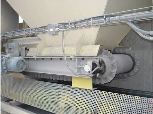
Source: Asphalt Institute
Figure 25. Cold-Feed Bin Feeder Belt
Each cold-feed bin opening is typically equipped with a flow sensor (see Figure 26) placed directly in the material stream. If a bin runs empty or the discharge opening becomes clogged, a “no-flow condition” alert is sent to the plant computer.
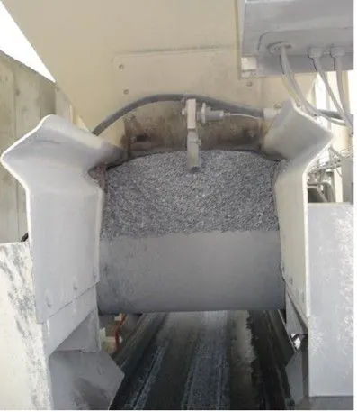
Source: Asphalt Institute
Figure 26. Bin Feed Aggregate Sensor
Because a uniform flow of properly sized aggregates is so important to consistent production, a check should be made before and during production to be certain that the feeder system is functioning properly. The following conditions are important for maintaining uniform flow and consistency:
- Correct sizes of aggregates in stockpiles and cold bins.
- No segregation of aggregate stockpiles.
- Accurately calibrated and secured feeder gates.
- No obstructions in feeder gates or in cold bins.
- No material clumping causing “bridging” that interrupts uniform flow.
- Correctly functioning bin vibrators, if equipped, to prevent bridging.
- Correct speed control settings.
4.3.3 Mineral Filler/Hydrated Lime Additive System
Extremely fine materials, generally referred to as the “dust” (minus 0.075-mm sieve) fraction of the aggregate gradation, are a critical component of any durable asphalt mix.
Mineral filler, such as hydrated lime, Portland cement, fly ash, limestone dust, or baghouse fines, should be stored in a silo or other appropriate container and delivered to the plant through a vane feeder system (see Figure 27) or small weigh hopper. The speed of the feeder is calibrated to the aggregate being delivered to the drum. The silo is normally equipped with an aerating system to keep mineral filler from packing into a tight mass and bridging the feeder opening. If the flow of filler is restricted, the vane feeder will still rotate, but no material will be sent to the plant.
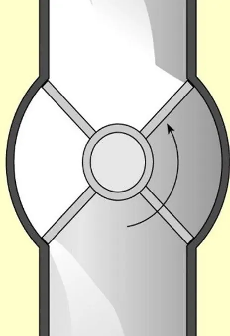
Source: Asphalt Institute
Figure 27. Vane Feeder Schematic
Once metered, a pneumatic system or auger is used to move the material to the required location. In a drum mixer, it is typically located near the binder supply line in the drum. This proximity allows the liquid binder to capture the extremely fine material, preventing it from being diverted back to the dust collection system. Terminating both supply lines under a hood or impinging shroud (see Figure 28) will add extra protection by separating the fine material from the high-velocity airstream flowing through the dryer.
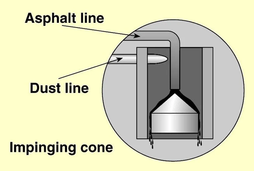
Source: Asphalt Institute
Figure 28. Drum Mixer Impinging Hood or Cone
To continuously meter the dust, storage silos typically make use of a weigh hopper or pod to accurately meter the rate of material flowing from storage into the mixing process. If this method is not available, frequent checks on the calibration of the feeding and weighing mechanisms should be performed.
Some agencies require the use of hydrated lime as an anti-stripping agent. There are many methods in use that successfully incorporate hydrated lime into a mix. A common method is to add hydrated lime directly to moist aggregate or combine it with water to make a slurry and then mix it with the aggregate in a separate pugmill. Generally, the lime-aggregate mixture is fed directly into the plant after mixing. However, an aggregate treated with a lime slurry mixture may be stockpiled to allow for additional marinating and drying before introduction into the plant for mixing. For more information on the use of hydrated lime as an anti-stripping agent, refer to Section 3.6.3.
4.3.4 Reclaimed Asphalt Pavement
The cold-feed system for handling RAP is essentially the same as the conventional cold-feed system for new aggregate. On most plants, as shown previously in Figure 21 and Figure 22, a separate cold-feed bin is used. The bin (or bins) is like the cold-feed bins used for aggregate except that all four sides of the RAP feed bins are usually much steeper. The steeper sides reduce the tendency of the reclaimed material to bridge the opening at the bottom of the bin. The RAP should be passed through a scalping screen to remove any oversized pieces of asphalt mixture or deleterious material.
It is an important point to keep in mind that RAP sources must be properly and randomly tested for consistency prior to producing the mixture. If RAP consistency is variable, using a higher percentage will increase the probability that the final product will be out of specification. This is one reason why some specifying agencies frequently ask for RAP sources to be stockpiled separately and why RAP percentages are often limited in the final product.
RAP sources must be properly and randomly tested for consistency prior to producing the mixture.
One way to reduce RAP variability is to fractionate it into two sizes—a fine material and a coarse material. The splitting screen size may range from 9.5 to 19 mm (3/8 to 5/8 of an inch). The material is then proportioned into the mix as if it were two sources of material. Additional information concerning recycled material is available in Section 3.3.9.
4.4 Aggregate Drying and Heating
From the cold-feed bins, aggregates are delivered to the dryer drum. The dryer accomplishes two things: it dries the aggregate and heats the aggregate to the required temperature.
4.4.1 Aggregate Dryer
The dryer is a sloped, rotating cylinder ranging from about 5 to 10 ft (1.5 to 3 m) in diameter and 20 to 40 ft (6 to 12 m) in length (see Figure 29). It has an oil or gas burner with a blower fan to provide the primary air for combustion of the fuel. The exhaust fan is a critical element that pulls the heated gases through the dryer and assists in the complete combustion of burner fuel. The exhaust fan is located beyond the dryer, at the end of the dust control equipment (discussed further in Section 4.7).
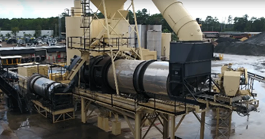
Source: National Asphalt Pavement Association
Figure 29. Typical Batch Plant Dryer
The inside shell of the drum has bolted-on or welded-on longitudinal troughs and channels, called flights, which lift the aggregate and drop it in a continuous shower or “veil” through the heated gases flowing through the dryer (see Figure 30). The slope of the dryer; its rotation speed, diameter, and length; and the arrangement and number of flights all combine to determine the time the aggregate will spend in the dryer.

Source: Asphalt Institute
Figure 30. Uniform Veil of Aggregate in Dryer
Near the open flame area of the burner, also known as the combustion zone, special flighting traps the aggregate near the wall of the dryer and carries it over the top of the flame. This prevents individual particles from passing through the flame and interfering with complete fuel combustion. Maintenance of the flights in the drum to produce a uniform veil of aggregates (see Figure 31) across the drum is necessary to efficiently produce a consistent mix.
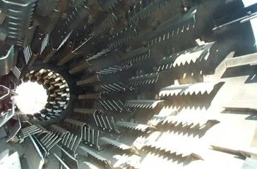
Source: Stansteel/Hotmix Parts & Supply
Figure 31. Different Types of Dryer Flights
4.4.1.1 Aggregate Dryer Types
There are two basic types of dryers: parallel-flow and counterflow. They are named for the relationship between the flow of the aggregate and the flow of the hot gases within the dryer. Regardless of the dryer style, the principles of drying aggregate are the same.
In parallel-flow dryers (see Figure 32), the aggregate and the air flow in the same direction. Cold aggregate is introduced into the dryer at the same end as the burner (the higher end of the drum), and the materials flow toward the lower end of the dryer parallel to the airflow.
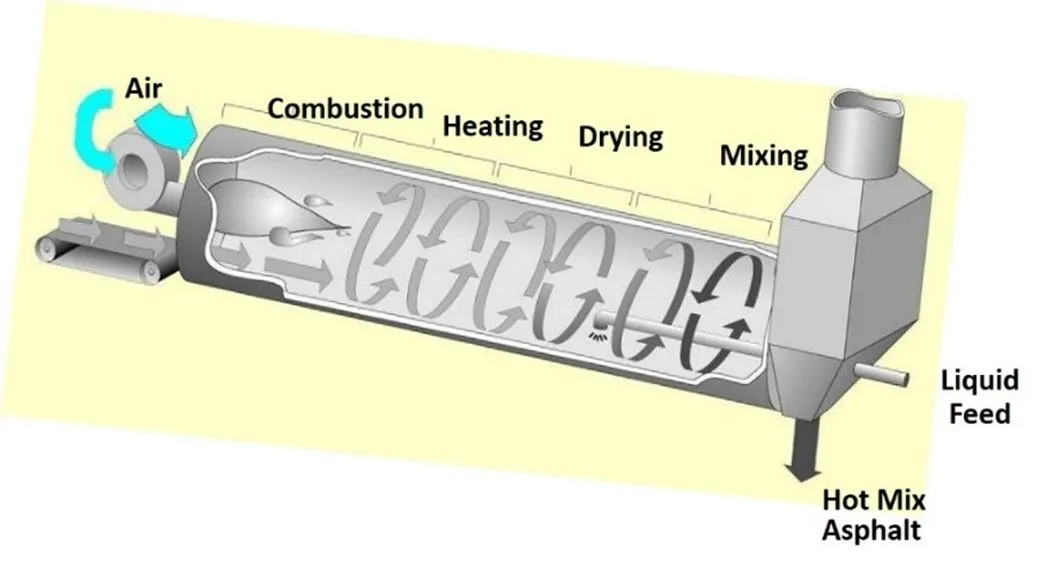
Source: IIT Kharagpur
Figure 32. Parallel-Flow Dryer
In counterflow dryers (see Figure 33), the aggregate and air flow in opposite directions, counter to each other. The burner is in the lower end of the drum and the aggregate is carried down through the drum against the airflow. Counterflow dryers are more common because they provide more efficient heat transfer than parallel-flow dryers.
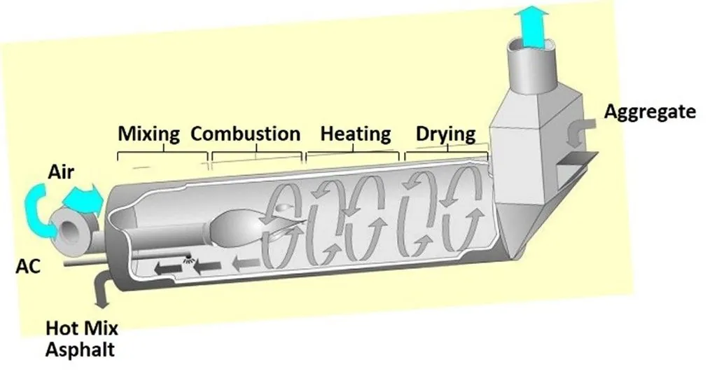
Figure 33. Counterflow Dryer
4.4.1.2 Aggregate Dryer Capacity
The drying process controls the overall production rate of the entire facility. Asphalt mix cannot be produced faster than the aggregate can be dried and heated. Dryer capacities are rated for heating and drying aggregate at a specific moisture content (typically 5 percent). If the aggregate moisture content is higher, the quantity of aggregate being fed to the dryer must be reduced to dry the aggregate properly. Consequently, there is a drop in the dryer’s production. Dryer slope, flighting, product temperature, aggregate type, atmospheric conditions, and elevation will also impact dryer performance.
If the aggregate moisture content is higher, the quantity of aggregate being fed to the dryer must be reduced to dry the aggregate properly.
Aggregate moisture content should be determined at least twice a day and more often if moisture conditions change, such as after rainfall. The average moisture content of the aggregate coming into the plant dryer or drum mixer is needed by the plant control system to permit proper setting of the burner controls, calculation of the dry weight of the incoming aggregate, and determination of the binder supply for drum-mix plants.
4.5 Batch Plants
Batch plants (shown in Figure 34) get their name from the fact that during operation they produce asphalt mixture in batches, one batch at a time, one after the other. The size of a batch varies according to the capacity of the plant’s pugmill (the mixing chamber where aggregate and asphalt binder are blended). Batch sizes can vary from 2,000 to 10,000 lbs (900 to 4,500 kg).
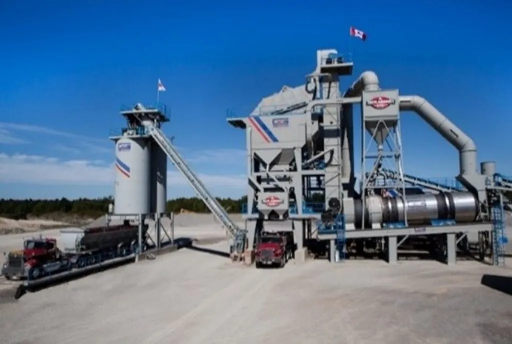
Source: Gencor Industries
Figure 34. Asphalt Batch Plant
4.5.1 Operations
As discussed earlier, the basic operations of both batch and drum-mix plants are similar except for the aggregate and asphalt mixing procedures. Material storage and handling, aggregate cold feeds, and aggregate heating and drying, as well as emissions control, are all quite similar for batch and drum-mix plants. This section will focus on the mixing operations that are unique to a batch plant.
4.5.2 Screening and Storage of Hot Aggregate
After the aggregate has been heated and dried, it exits the dryer into a hot elevator. The hot elevator is a nearly vertical, enclosed bucket conveyor that carries the aggregate to the top of the “batching tower” (see Figure 35). The aggregate is discharged from the elevator into a screening unit. The hot aggregate passes over a screening unit that separates it into various-size fractions and deposits those fractions in hot bins.
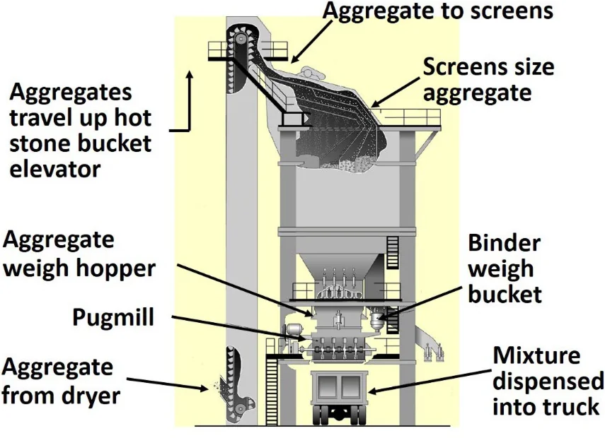
Source: Asphalt Institute
Figure 35. Batching Tower
The screening unit includes a set of several different-size vibrating screens inside a large housing. The screens separate the aggregate into specific sizes. The first screen is a scalping screen that removes oversized aggregate. This is followed by two to four screens,decreasing in size from top to bottom. The sizes of the screens used will depend on the plant and the gradation of the aggregate for the mix being produced (see Figure 36). The screens are designed to allow the finest particles to drop completely through to the first hot bin, and larger particles move along the screens to be deposited into the subsequent bins.
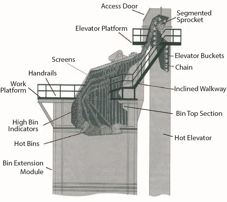
Source: Asphalt Institute
Figure 36. Screening Decks and Hot Bins
4.5.3 Hot Bins
Hot bins are located directly below the screening unit and used to store the heated and screened aggregates. Hot bins have indicators that tell when the aggregates fall below a certain level. These indicators may be either electronic or mechanical. Each bin should also be equipped with an overflow pipe or a high bin indicator to prevent excessive amounts of aggregate from spilling into the other bins. When a bin severely overfills, the screen above it rides on the overloaded aggregate, resulting in a heavy carryover and possible damage to the screen.
Hot bins are referred to by their total capacity. This can be as low as 20 tons for a small, portable batch plant to as large as 300 tons for a large, stationary plant. A very common capacity is in the range of 40 to 80 tons (36 to 72 tonnes).
Not all aggregate passes through the screening deck and hot bins. Mineral filler and dust returning from the baghouse are fed directly into the weigh hopper and weighed as a separate component.
4.5.4 Hot-Bin Sampling
Batch plants are equipped with devices for sampling hot aggregate from the bins. Most plants utilize a sample container mounted at the end of a control rod. When placed under the hot-bin feeder or gate, the containers catch a complete cross-section of the aggregate flow as it drops out of the bin. Some plants have a device to divert the flow of aggregate from the hot bin to a sample container. It is essential that such containers be properly located when taking the sample so that they collect a representative sample of the material.
During production, as the aggregate flows over the plant screens, the finest particles fall first into one side of each bin, and coarser particles travel along the screen to the other side of each bin. When material is drawn from the bin, the aggregate stream consists predominantly of finer material on one side and coarser material on the other. Therefore, the position of the sampling device in the stream of material discharged from a bin determines whether the sample will be composed of a finer portion, a coarser portion, or an accurate representation of the material in the bin. This condition is especially critical in the first or Number 1 (finest aggregate) bin since the material in this bin strongly influences the amount of asphalt binder required in the mix.
4.5.5 Calibration
Normally it is the contractor’s responsibility to calibrate the asphalt plant; however, agency inspectors are often required to observe and be aware of the procedures used to arrive at an aggregate combination that meets the JMF.
It is important to understand that the hot-bin percentages used to calculate batch weights are different than the cold-feed bin percentages. For the plant to produce the desired JMF specified in the mix design, the content of each hot bin must be analyzed. Once the plant is started and allowed to reach proper operating condition, a sample of aggregate is taken from each hot bin and analyzed. Once the gradation of material in each hot bin is determined, the exact percentage by weight from each hot bin to meet the design mix can be determined.
The hot-bin percentages used to calculate batch weights are different than the cold-feed bin percentages.
It is possible for a batch plant to change mixture types from truckload to truckload. However, if the aggregate being supplied by the cold feed is not balanced with the aggregate discharge from the hot bins, the system can become unbalanced and result in one bin overflowing and another being starved of material. The smaller the hot bin size, the more easily it becomes unbalanced. The plant operator can only change the amount of hot-bin material being discharged into the mixer. This can be altered for a load or two (depending on the size of the hot bins), but when the plant becomes severely unbalanced, production will need to cease, and the plant cleared of excess aggregate in the bins to reestablish a balanced condition. Continual use of overflow chutes from the hot bins indicates the mixture being produced is not in sync with the gradation of the material being proportioned by the cold-feed system.
4.5.6 Drawing Material from the Hot Bins
The aggregate is drawn from each hot bin, one bin at a time, into a weigh hopper positioned above the actual mixing chamber or pugmill. The weigh hopper is continuously weighed, and the contribution of each hot bin is accurately determined for each batch of mix produced.
Usually, the coarsest aggregate is drawn (or pulled) first, the intermediate size aggregates next, and the finest aggregate last. This system allows the most efficient utilization of the available volume in the weigh hopper since the finer aggregates will partially penetrate the voids in the coarser aggregates. This information is normally entered into a computer that controls the opening and closing of the bins to obtain the correct amount of aggregate from each hot bin. Figure 37 illustrates how the cumulative scale settings are used to control the weight of aggregate drawn from each bin.
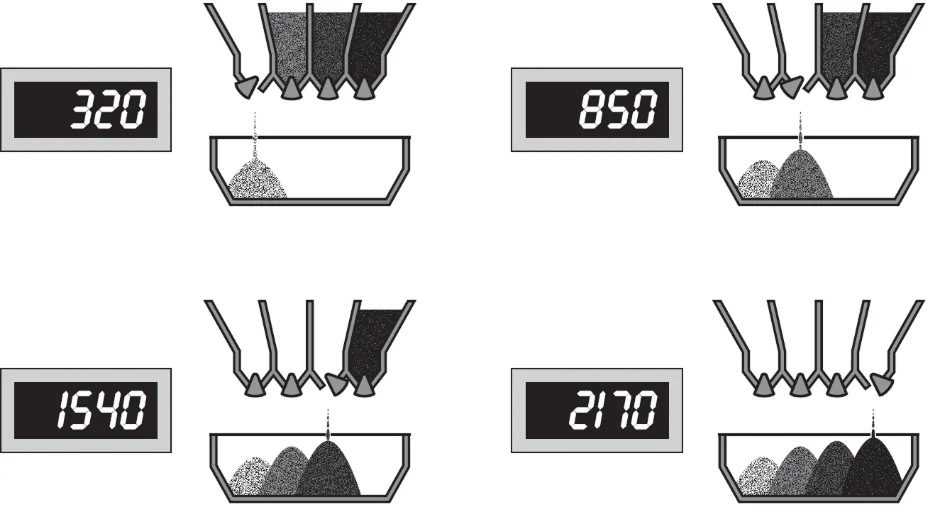
Source: Asphalt Institute
Figure 37. Cumulative Hot-Bin Batching
4.5.7 Introducing the Asphalt Binder
From the weigh hopper, the aggregate is deposited into the plant’s pugmill (mixing chamber), where it is blended with the proper proportion of asphalt binder. In a typical plant system, the binder is weighed separately in weigh buckets—which are enclosed, heated, and sealed units—before being introduced into the pugmill. When the weight of asphalt binder in the bucket reaches a predetermined level, a valve in the delivery line closes to prevent the excess binder from being discharged into the bucket. The binder is then pumped through spray bars into the pugmill (see Figure 38).
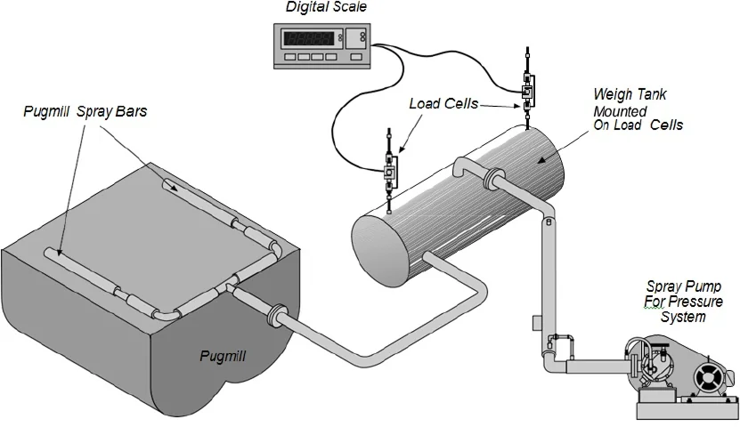
Asphalt cement is weighted separately in a load cell-mounted weigh tank.
Source: Asphalt Institute
Figure 38. Batch Plant Binder Supply System
4.5.8 Pugmill Mixing
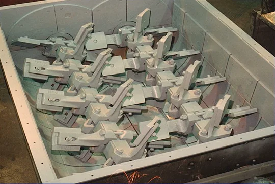
Once the batching of aggregate and asphalt binder is completed, the aggregate is transferred to a mixing chamber, called a pugmill (shown in Figure 39), which is located immediately below the weigh hopper.
Typical batch plants use a twin-shaft pugmill, which consists of a mixing chamber with two horizontal shafts, on which several cross arms are mounted. Pugmills are lined with sacrificial steel wear plates to absorb the scouring effect of mixing hard, angular aggregate particles.
Source: Asphalt Institute
Figure 39. Batch Plant Pugmill
At the end of each cross arm is a metal plate, commonly called a mixing paddle. These paddles must be adjusted to avoid dead zones in the pugmill. Dead zones are areas where the materials are not properly agitated. To avoid this situation, the paddles should be adjusted so that the clearance between the paddle tips and the mixer liner is less than one-half the maximum size aggregate used in the mix. Worn or broken paddles should be replaced as soon as possible.
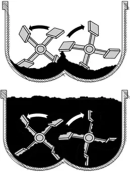
If the pugmill is overfilled or underfilled, nonuniform mixing will occur (see Figure 40). With too little material in the pugmill, the paddles are not able to adequately mix the material. If the pugmill is overloaded, part of the material will tend to float on the top of the batch and not be thoroughly mixed. These situations can be avoided by following the manufacturer’s rated batch size. Normally the manufacturer’s rating is based on a percentage of the pugmill live zone. This live zone is the net volume of the inside of the pugmill below a line extending across the top arc of the mixing paddles. The volume of the shafts, cross arms, paddles, and liner is not included in this volume. In most cases, the maximum operating efficiency of a pugmill is achieved when the paddle tips are barely visible at the surface of the material during mixing.
If the pugmill is overfilled or underfilled, nonuniform mixing will occur.
Source: Asphalt Institute
Figure 40. Incorrect Pugmill Operation
The complete mixing cycle is the blending of asphalt binder, aggregates, and mineral filler to produce mix. The length of time between the opening of the weigh-box gate and the opening of the pugmill discharge gate is referred to as the batch mixing time. The batch time typically consists of two stages: a dry mixing stage and a wet mixing stage. The dry mixing stage is a short portion of the batch time used (10 seconds or less) to mix the aggregates before introducing the binder. The wet mixing stage is the mixing time after the binder has been introduced into the mix. The total batch mixing time must be long enough to produce a homogenous mixture of evenly distributed and uniformly coated aggregate particles. To monitor batch mixing time, most job specifications require the use of some type of timing device.
The total batch mixing time must be long enough to produce a homogenous mixture of evenly distributed and uniformly coated aggregate particles.
Mixing time may be set within specification limits for each mix in any given plant by the procedure described in AASHTO T 195 or ASTM D2489, Determining Degree of Particle Coating of Bituminous-Aggregate Mixtures. This system bases the degree of mixing on the percentage of coarse particles that are 100 percent coated with asphalt binder and correlates it with mixing time. Only coarse particles are used in this procedure because they are the last to be coated in the mixing process.
4.5.9 Batch Plant Automation
A batch plant control room (shown in Figure 41) typically has the following plant control areas:
- A master motor control console with start/stop switches for all plant motors, which are interlocked for safety and plant protection.
- A computer system that controls the motor starts and stops in a pre-planned and programmed sequence so they cannot be started unless previous conditions are met, i.e., the main conveyor belt cannot be started unless the dryer drum is turning, or the burner cannot fire up unless the exhaust fan is running.
- A burner control console with start/stop switches, increase/decrease switches, and the safety circuits required for the burner.
- A cold-feed control console with start/stop switches and increase/decrease switches to control the feed from individual cold bins to the dryer. Many cold-feed control consoles have manual/automatic selector switches that allow the operator to control the feed from each bin manually or to recall a cold-feed mix formula from memory, select the desired production rate, and automatically feed the dryer to match the batch cycle requirements. A separate computer is sometimes found dedicated to this type of cold feed automation.
- A computerized batch automation that resides in a batch control console.
- A draft control and air emission-control console that houses controls for the exhaust fan, dryer draft, and air emission-control equipment.
- Mineral filler, baghouse fines return, hydrated lime control, or other additive control panels, if that equipment is required for the project.

Source: National Asphalt Pavement Association
Figure 41. Batch Plant Control Room
4.5.10 Recycling with a Batch Plant
All recycling methods in batch plants utilize conductive heat transfer instead of convective heat transfer. Conductive heat transfer is accomplished by mixing cold recycled material with hot aggregate. Convective heat transfer is accomplished by exposing cold aggregate to hot gases. In batch plants, regardless of the recycling method used, superheated hot virgin aggregate is used to heat the cold, moist RAP. A brief discussion of common batch plant recycling and heat transfer methods is described below.
4.5.10.1 Weigh-Box Recycling Technique
With the weigh-box method of recycling, cold (unheated), moist RAP is added to the weigh hopper, where the batch controller weighs it as an additional aggregate material. The feed bin for the RAP and the elevated conveyor that is required to reach the weigh hopper typically have large motors and pneumatic clutches with brakes so they can be started and stopped instantly. This facilitates feeding just the right amount of RAP into the weigh box.
The RAP is then mixed with the superheated virgin aggregates in the weigh hopper. Conductive heat transfer occurs in the weigh hopper and the pugmill throughout the dry mixing stage. During the heat transfer process, the moisture in the RAP generates a significant amount of steam. The pugmill and weigh hopper area must be enclosed and vented to the emission-control system to control this instantaneously large volume of steam and dust.
While recycled mixes with up to 50 percent RAP content can theoretically be produced with this method, in day-to-day practical field conditions, it is rare to see RAP percentages higher than 25 percent with the weigh-box heat transfer method. This is because RAP moisture contents typically run in the 3- to 5-percent range, and elevating the aggregate temperature beyond 600 °F (315 °C) is difficult due to dryer limitations. Also, dryer exit gas temperatures can impose a practical limit if baghouses are used in the plant. The filter fabric used in the bags of the baghouse has temperature limitations, and a massive increase in fuel consumption is required to obtain the required aggregate temperature.
4.5.10.2 Pugmill Recycling Technique with Separate RAP Weigh Hopper
This method of recycling uses a separate weigh hopper for RAP, which empties its batch component into the pugmill. Typically, a high-speed slinger conveyor is used to convey RAP from the RAP weigh hopper to the pugmill, although a chute or high-speed screw conveyor can also be used. The same heat transfer, steam release, and practical limits apply to this approach as apply to the weigh-box method of batch plant recycling. By adding an additional weigh hopper to the batch facility, the RAP is conveyed into and weighed in its own hopper while the virgin asphalt binder and virgin aggregates are being weighed separately, which slightly reduces the batching time.
4.5.10.3 Bucket Elevator Recycling Technique
This approach to batch plant recycling eliminates the steam release typical of the mixer and pugmill heat transfer methods. In the bucket elevator recycling method, cold, moist RAP is mixed with the superheated virgin aggregate as the aggregate exits the dryer and enters the bucket elevator.
The continuous steam release resulting from conductive heat transfer occurs in the buckets as the virgin aggregate/RAP mixture makes its way to the screen deck. The steam released from the RAP is carried away by the fugitive dust ductwork already fitted to the bucket elevator and screen deck.
Because the RAP is being continually blended with the virgin aggregate, belt scales are used on both the conveyor feeding virgin aggregate into the dryer and the conveyor feeding RAP into the bucket elevator. The scales ensure the maintenance of a proper ratio of RAP to virgin aggregate.
Gradation control for mix production is accomplished in one of two ways, and both are different from that in a batching facility producing completely virgin mixes. In the first method, the RAP and virgin aggregate are both screened together over the screen deck, and the composite mixture is separated into the different hot bins in the tower. Each hot bin is sampled for asphalt binder content and gradation. The binder content of the material must be determined in each hot bin. Gradations of the hot-bin samples must then be evaluated, and individual hot-bin percentages calculated based on the recovered gradations from each supply bin. The asphalt binder content reclaimed from the RAP is then determined based on the extraction results, and the new liquid binder requirement for each batch is established. It must be assumed that the RAP is consistent not only in the recovered stone gradation but also in the asphalt binder content and particle size of the RAP itself.
This approach to mix production is more difficult than with a weigh-box or pugmill injection method; therefore, a second method, which utilizes a screen bypass, is frequently used. With this method, the only gradation control is at the cold-feed bins feeding the dryer, same as with drum-mix style plants. The virgin aggregate/RAP mixture is stored in a single hot bin in the tower and then weighed up as one pre-blended mixture in the aggregate weigh hopper. The mixture is diverted into one bin, typically the Number 1 bin, using a chute from the hot elevator to bypass the screen deck.
Many agencies allow this type of approach but usually also require belt feeders with variable-speed drives, speed displays, and total and proportional control over each feed bin. This is the same generic requirement used for feeder gradation control on drum mixer-style plants. Because the trip up the elevator is relatively short in duration, and because the RAP must be dry before it passes over the screens (or is stored in the combined RAP/aggregate bin), RAP percentages rarely run over 20 percent with this approach.
4.5.10.4 Introducing RAP into Heat Transfer Chamber or Dryer
This approach is essentially the same as the standard bucket elevator method, but RAP is added to the combustion area of the dryer and is shielded from the flame by a shroud or by extending the burner tube. Another difference is that steam release also begins in the dryer shell. An advantage of this process is that the virgin aggregate and RAP are already combined as they exit the dryer and enter the elevator.
Higher percentages of RAP can be achieved (25 to 35 percent is typical) than with standard bucket elevator methods because the RAP has a longer period for heat transfer to be completed. All other aspects of the standard bucket elevator method apply to this recycling approach.
4.6 Drum and Continuous Plants
Watch Video
Drum mixing simplifies the process of producing asphalt mixtures by eliminating the need for several major mechanical components when compared to batch plants. Operationally, the major difference between drum-mix plants and batch plants is that in drum-mix plants, the aggregate is not only dried and heated within the drum but also continuously mixed with the asphalt binder.
4.6.1 Operations
The mixing drum, or drum mixer, is where this type of plant gets its name. Because there are no gradation screens, hot bins, weigh hoppers, or pugmills in a drum-mix plant, aggregate gradation is totally controlled by the aggregate, RAP, and mineral filler cold-feed systems.
4.6.2 Drum-Mix Plant Operations and Components
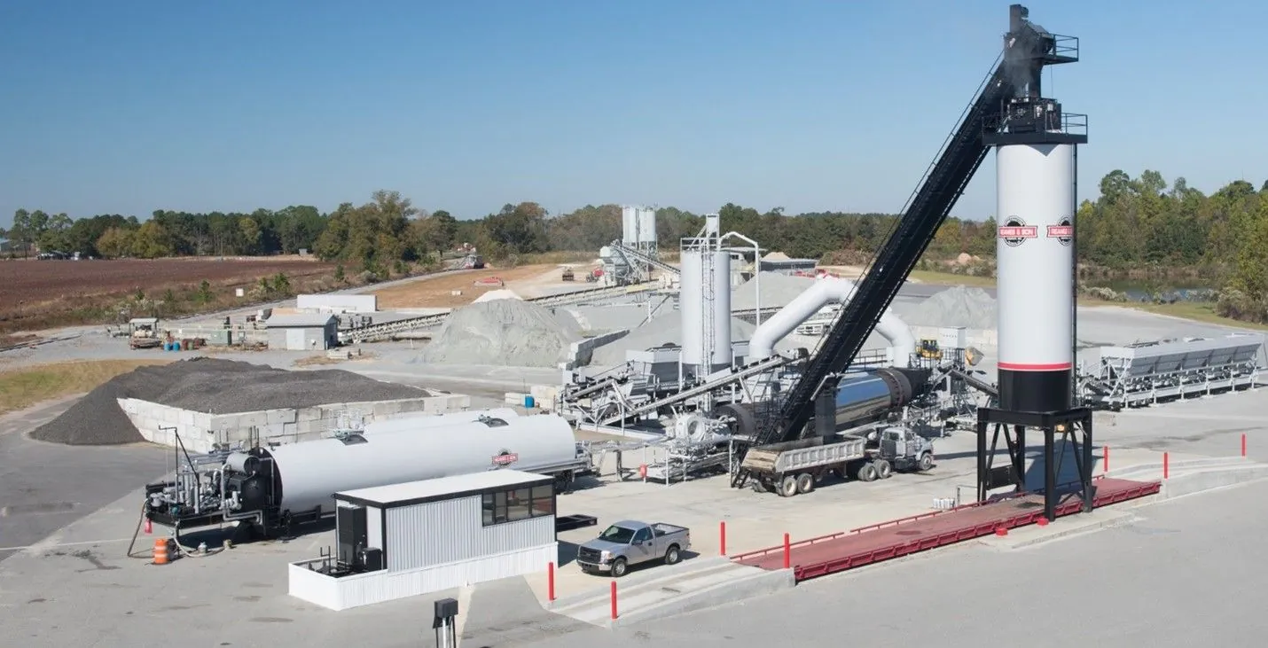
The components of the drum-mix plant are shown in Figure 42.
Source: Astec Industries
Figure 42. Typical Drum Mixer Layout
Individual aggregates are deposited in the cold-feed bins, from which they are fed individually in designed proportions onto a cold-feed conveyor. An automatic aggregate weighing system monitors the amount of aggregate flowing into the drum mixer. The weighing system is interlocked with the controls on the asphalt binder storage pump and a continuous metering system, which draws binder from a storage tank and introduces it into the drum. The asphalt binder and aggregate are thoroughly blended while rotating in the drum. A dust collection system captures excess dust escaping from the drum and mixing chamber. From the drum, the mix is elevated by a metal slat conveyor to the top of a surge bin or storage silo where it stays until loaded in a truck, as described in Section 4.9.
4.6.3 Aggregate Feed
In a drum-mix plant, mix gradation and uniformity depend mostly on the cold-feed system. Hence, it is essential the aggregate be correctly proportioned prior to its entry into the dryer/mixing drum. The most efficient way to accomplish this is with a multiple-bin cold-feed system equipped with precision belt feeders for the control of each aggregate.
Under each bin is a variable-speed belt feeder, which drops the metered aggregate onto a main collection belt that runs under all the cold-feed bins. The collection belt then transports the proportioned aggregate material to the main cold-feed conveyor belt, which carries the aggregate to the drum mixer.
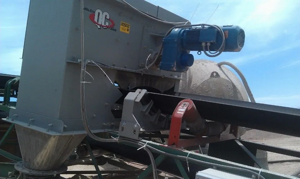
Most cold-feed conveyor belts are equipped with provisions to conveniently obtain representative samples of the full flow of material for gradation determination or for calibration. Such devices are usually installed at the end of the belt just prior to entry into the drum mixer. Devices are available that can be installed on the main belt to divert or collect accurate samples without stopping the belt (see Figure 43).
Source: Asphalt Institute
Figure 43. Conveyor Belt Sampling Device
Drum-mix plants require a continuous weighing system on the main cold-feed conveyor belt. As aggregate passes over the scale, they are continuously weighed and monitored by the hot-plant control system. No material should be diverted from or added to the conveyor belt after it passes the belt scale.
It is important to understand that the aggregate is weighed on the belt before drying. The total moisture content of the material entering the plant must be known so the asphalt pump can meter in the correct quantity of asphalt binder.
The moisture content of the cold-feed aggregate should be checked before beginning each day’s operation and again around mid-day. If the moisture content is believed to vary during the day, it should be checked more frequently. Some plants have moisture sensing devices that can sense changes in moisture content, coupled with the control system that compensates for moisture changes automatically.
4.6.4 Asphalt Binder Control with a Drum Mixer
Asphalt binder control in a drum mixer operation is done continuously. The asphalt binder is measured through a calibrated meter relative to aggregate flow after it has been corrected for moisture content and then combined with the aggregate in the mixing area of the drum.
The asphalt binder is measured through a calibrated meter relative to aggregate flow after it has been corrected for moisture content and then combined with the aggregate in the mixing area of the drum.
The asphalt binder content is interlocked to the aggregate flow. The monitoring system notes changes in the weight of aggregate over the belt scale and adjusts the asphalt binder flow to compensate for these changes.
The binder supply line runs continuously to keep pace with the aggregate weighbridge to deliver the proper ratio of binder in the mixing chamber. To confirm the metering system output is correct requires frequent verification of calibration or recalibration.
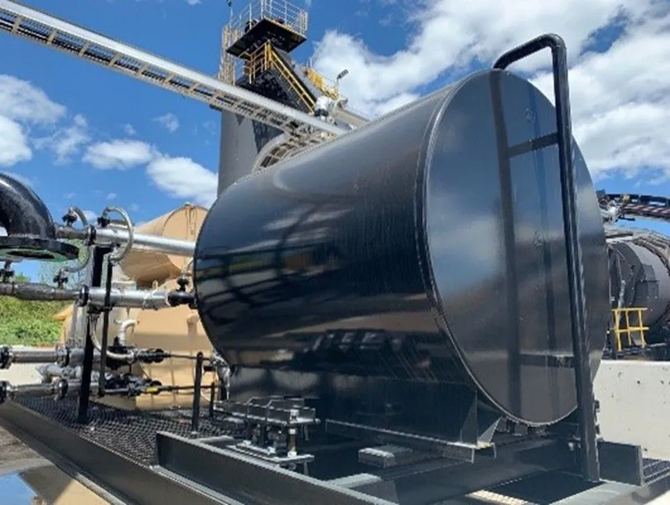
Taking a drum-mix plant offline to perform a calibration test can be very costly and time-consuming. Inline calibration tanks (see Figure 44) are an efficient way to calibrate asphalt metering systems without the downtime and risk associated with using the conventional tanker truck method.
Source: ALmix Industries
Figure 44. Stationary Asphalt Binder Calibration Tank
4.6.5 Aggregate Flow
Aggregate enters the primary zone of the drum, where the burner dries and heats it. The aggregate then moves to a secondary zone, where asphalt binder is added and the two are thoroughly blended. The mixture of hot asphalt binder and the moisture released from the aggregate produces a foaming mass that traps much of the fine material (dust) and coats the larger particles. It is important that the aggregate in the drum not only rotate with the revolving motion of the drum but also spread out sufficiently to make heating and drying of all particles quick and efficient. Drum mixers are equipped with specially designed flights to create a “veil” or curtain of aggregate at appropriate parts of the drum for obtaining maximum drying and minimizing exhaust gas temperatures.
4.6.6 Binder Flow
Asphalt binder is pumped from the binder storage tank and enters the mixing drum at the appropriate point in accordance with the plant design. When the asphalt binder is added into the drum, it is pumped into the drum’s lower end at about the same location that the mineral filler and/or baghouse fines are introduced. Adding asphalt binder and dust in close proximity allows the binder to trap a good portion of the fines and coat them before they are picked up by the high-velocity exhaust gas stream. The exhaust gases are passed through a dust collection system where any of the remaining dust is trapped and removed to meet emission requirements, as discussed in Section 4.7.
4.6.7 Recycling with a Drum-Mix Plant
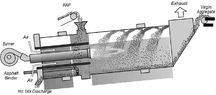
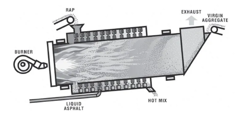
The introduction of RAP into a drum-mixing operation is quite different from the methods used in a batch plant. To minimize RAP binder damage and emission-control problems, it is necessary to add RAP via a split-feed system. In a split-feed system, new aggregate enters the drum in one location, and the RAP enters the system downstream, where it is not in direct contact with the burner flame. Figure 45, Figure 46, and Figure 47 illustrate typical RAP entry points for several types of drum-mix plants.
Source: Asphalt Institute
Figure 45. Counterflow Drum-Mix Plant
Source: Asphalt Institute
Figure 46. Unitized (Double-Barrel) Drum-Mix Plant
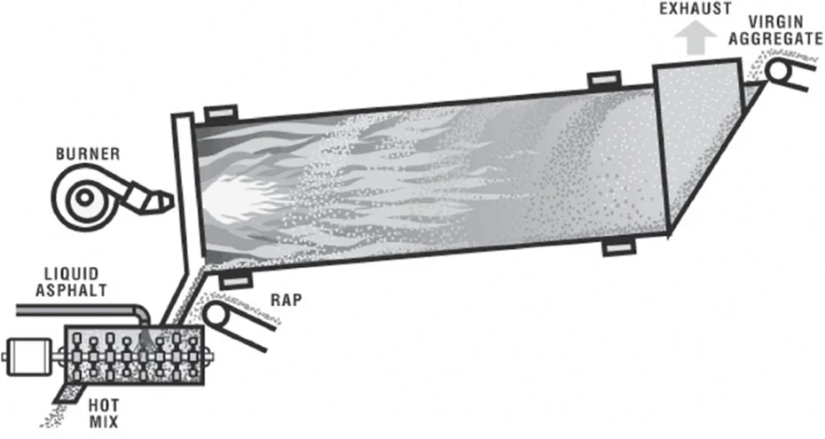
Source: Asphalt Institute
Figure 47. Counterflow Dryer with Separate Continuous Mixer
As mentioned in Section 4.5.10 regarding RAP in batch plants, a drum mixer also requires superheated virgin aggregate to transfer heat into the RAP and remove any moisture present. These conditions can present significant obstacles that can limit the maximum rate and amount of RAP mix that can be produced.
Normally, if 20 percent or less RAP is incorporated into a recycled mix and a split-feed system is used, minimal emission-control issues arise. As the percentage of RAP rises and the moisture content of the RAP increases, there is a greater potential for heat transfer and emission problems. A typical drum-mix plant requires carefully controlled production conditions to incorporate over 50 percent RAP in a recycled mix without major emissions and heat transfer issues.
4.7 Emission-Control System
The high-speed air flowing through the dryer that carries away exhaust gases also removes small, dust-sized particles (smaller than 0.075 mm) from the aggregate blend. Because this dust is part of the mixture design, it must be captured and returned to the mix being produced. Removing the dust from the exhaust stream with high-efficiency emission-control equipment prevents plant-produced dust emissions from exceeding local, State, and Federal air quality limits.
4.7.1 Basics of Dust Collection
The amount of airborne dust is a function of the material being dried, the velocity of the air in the dryer, and the location of the binder injection point that captures the smaller particles.
The emission-control system on most asphalt plant facilities generally consists of primary and secondary dust collectors. The dust collectors are situated downstream of the dryer and filter the air that exits the drum.
4.7.2 Primary Collectors
The purpose of the primary collector is to collect and remove the larger dust particles contained in the exhaust gas stream. The typical primary collectors are called the knockout box or the cyclone collector.
The knockout box is the simplest type of primary collector (see Figure 48). The exhaust gas flows through an expanded chamber, causing the airspeed to decrease. The chamber also contains plates to cause a change in the direction of airflow. The speed reduction and direction changes cause the larger dust particles to drop out of the airstream to the bottom of the box, where they are reintroduced in the dryer.
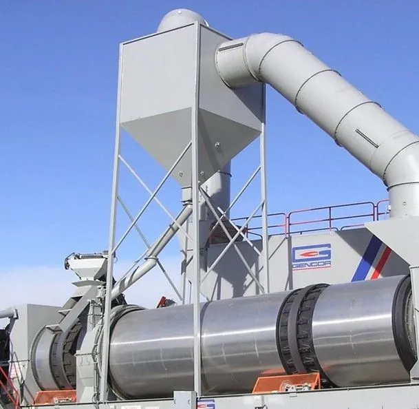
Source: Gencor Industries
Figure 48. Knockout Box Returning Coarse Fines to the Dryer
Cyclone collectors are more efficient than knockout boxes and operate on the principle of centrifugal separation. The exhaust stream circulates inside the collector (shown in Figure 49), and particles hit the outside wall and drop to the bottom of the cyclone. Speed and directional changes also assist as the exhaust is discharged through the top of the collector. The fines collected at the bottom of the cyclone are picked up by a dust-return auger and may be returned to the plant or removed.
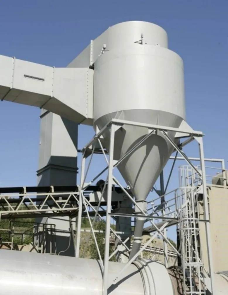
Source: Asphalt Institute
Figure 49. Cyclone Collector Returning Coarse Fines to the Dryer
4.7.3 Secondary Collectors
The purpose of the secondary collector is to filter out the finest dust particles. The most common type of secondary collector is referred to as a baghouse. A baghouse (see Figure 50) is a large metal housing containing hundreds of heat-resistant fabric filter bags. A typical unit may contain as many as 800 bags. It operates on a principle similar to a vacuum cleaner. The dust-laden exhaust gases are pulled through the filter bags supported on long wire cages to prevent collapse. The dust is trapped on the outside of the bag as the air passes through the filter cloth to the clean air side, effectively cleaning all the dust from the exhaust stream. When properly operated, baghouses can be very efficient, removing over 99 percent of the dust from the dryer exhaust.
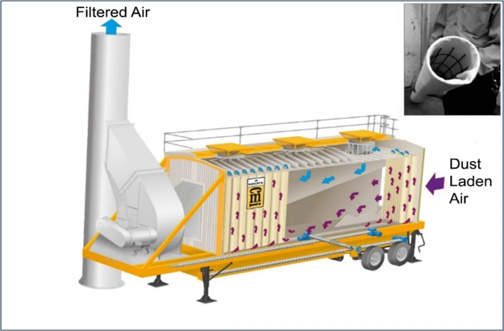
Source: CMI Roadbuilding, Inc.
Figure 50. Baghouse Dust Collector
Dust continuously collects on the outside of the fabric filter while the dryer is in operation. Periodically, a pulse of air is passed through the bag in the opposite direction, causing the bag to flex in reverse. The collected dust drops off the bag and falls to the bottom hopper of the baghouse. This collected dust can either be returned to the mix production process or removed. When dust is returned to the plant process, certain operational practices are important to keep the dust return uniform and consistent. Non-uniform introduction of baghouse fines back to the plant can cause erratic volumetric test results. Refer to Section 4.3.3.
4.8 Temporary Mixture Storage
To prevent plant shutdowns due to interruptions in paving operations or shortages of haul trucks, most asphalt plants are equipped with either one or more storage silo(s) or a surge bin for temporary storage of asphalt mix. As the fresh mix exits the plant, it is deposited onto an enclosed drag-slat type of conveyor that takes it to the top of the storage silo or bin, where it enters the bin and is held until discharged into trucks from the bottom.
Insulated storage silos (shown in Figure 51), with capacities as high as several hundred tons, can store mixture for several hours. Extended storage times will impact the volumetric properties of the mix and may prematurely age the binder. For this reason, most agencies have specifications that limit the length of time a mix can be held in storage.
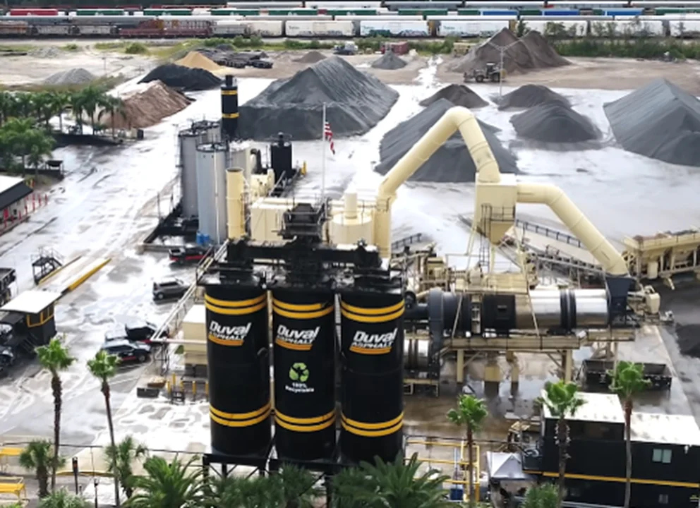
Source: Duval Asphalt
Figure 51. Insulated Storage Silos
Portable drum-mix plants equipped with self-erecting storage structures are most frequently used at remote or temporary plant sites. These non-insulated surge bins (shown in Figure 52 and Figure 53) are smaller and can store mix only for relatively short periods of time.
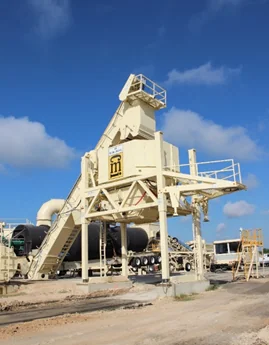
Source: Asphalt Institute
Figure 52. Portable Surge Bin
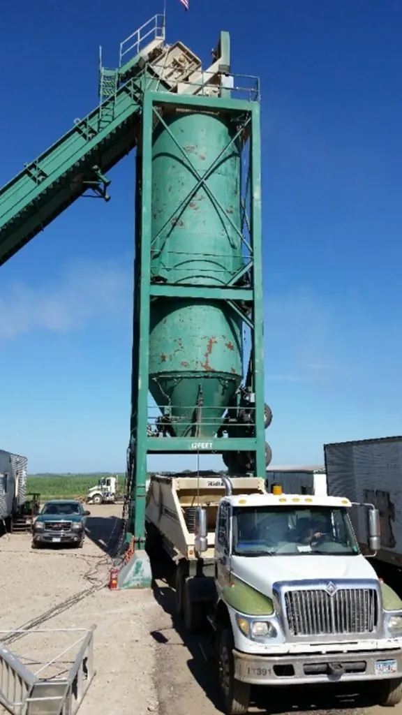
Source: Asphalt Institute
Figure 53. Portable Storage Silo
Silos work well if certain precautions are followed, but they can be a major source of segregation if the mix is not introduced into the silo properly. Mix should never be allowed to flow continuously into a storage silo; particle size differences and momentum will cause the mix to segregate. Typically, a small batcher (or holding bin) is placed under the drag-slat conveyor with its opening directly aligned on the centerline of the silo. Once a pre-set amount is accumulated, gates in the bottom of the batcher automatically cycle fully open and fully closed, releasing the mix in a single mass (see Figure 54). During continuous operation, the batcher should never completely cycle empty, and the mix level in the storage silo should be maintained between one-third and two-thirds of the silo capacity to minimize segregation.
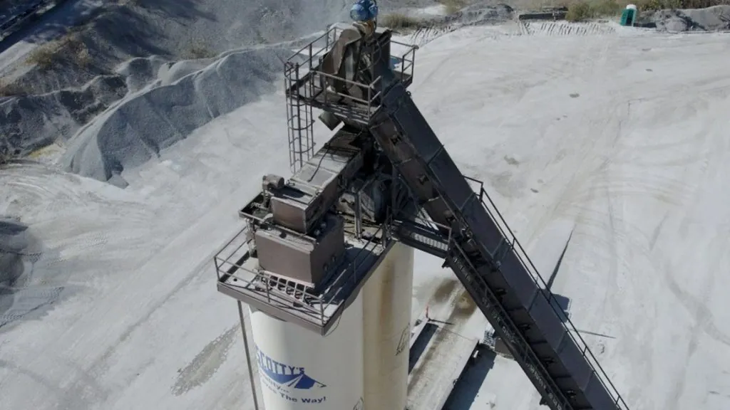
Source: National Asphalt Pavement Association
Figure 54. Silo Batcher
4.9 Weighing and Loadout
From the temporary storage silo, asphalt mix is deposited into trucks ready to be hauled to paving sites. (See Chapter 6 for truck loading procedures.) The quantity of mixture delivered from plant to paving site can be determined by any of three methods:
- Using a batch plant’s automatic recording system.
- The system records the accumulated weight of individual batches dropped directly into a truck from the pugmill. The internal plant scales should be calibrated and certified to use this method successfully.
- Using load cells attached to the support legs of a storage bin
- he load cells collectively accumulate the subtraction of weight from the bin as a truck is loaded.
- Load cells are calibrated and certified as accurate.
- Weighing loaded trucks on scales.
- The scales directly indicate the tare weight of the truck and net weight of the mix.
- The scales should be level, horizontal, and of sufficient length to weigh all truck axles at one time. The most common type of truck scale used is the beam scale (see Figure 55).

Source: National Asphalt Pavement Association
Figure 55. Truck Scale Under Storage Bins
The accuracy of any truck scale or weigh system should be checked periodically. Random truckloads selected throughout production and weighed on an alternative, certified scale provide for a good check on the accuracy and calibration of the weigh system being used.
The accuracy of any truck scale or weigh system should be checked periodically.
4.10 Safety
Watch Video
Personnel working at an asphalt plant must always be safety-conscious and on the alert for potential dangers to personnel and property. Safety considerations cannot be overemphasized.
Safety considerations at an asphalt plant include the following:
- Dust is not only a threat to lungs and eyes, but it may contribute to poor visibility, especially when trucks, front-end loaders, or other equipment are in use around the stockpiles or cold bins. Reduced visibility in work traffic is a prime cause of accidents.
- Noise can be a significant hazard. It is harmful to hearing and can distract workers’ awareness of moving equipment or other dangers.
- Moving belts should be a constant concern, as should belts to motors and sprockets and chain drives. All pulleys, belts, and drive mechanisms should be covered or otherwise protected. Loose clothing that can get caught in machinery should never be worn at an asphalt plant.
- Good housekeeping is essential for plant safety. The plant and yard should be kept free of debris, pipes, hoses, or other obstacles that can cause a trip and fall hazard.
- High-voltage lines are required to distribute electrical power to all the major plant components. Power lines should be properly mounted or buried and protected. Any loose connections, frayed insulation, or improperly grounded equipment should be repaired immediately.
- Plant workers should not work on or near stockpiles or cold-feed bins while the plant is in operation. With limited sightlines, loader operators who are focused on stockpile management and keeping cold-feed bins properly charged can easily overlook a person on the ground. Equipment training regarding blind spots is encouraged.
- Burner flames and high temperatures around plant dryers are obvious hazards. Installing control valves that can be operated from a safe distance on all fuel lines helps reduce the danger. Flame safety devices also should be installed on all fuel lines. Smoking should not be permitted near asphalt or fuel storage tanks. Frequent checks should be made for leaks in oil heating lines and jacketing on the asphalt distribution lines. Safety valves should be installed and be in good working order on all lines. Screens, barrier guards, and shields should be installed as protection from steam, hot asphalt, hot surfaces, and similar dangers.
- For workers around hot liquid asphalt binder, all shirts should be long-sleeved, completely buttoned, worn tucked in, and cuffs buttoned at the wrist. Gloves with gauntlets that extend up onto the arm should fit loosely so that they can be flipped off easily if accidentally covered with hot asphalt. Pants without cuffs should extend over boot tops.
- Workers should use extreme care when moving around plant components, observing the screens and hot bins, and collecting samples. There should be covered or protected ladders or stairways to provide safe access to all parts of the plant. All stairs and platforms should be provided with secure handrails. All workers around the plant site should always wear a hardhat.
- Traffic patterns should be planned with both safety and convenience in mind. Trucks entering the plant to pick up a load of hot mix should not have to cross the path of loaded trucks leaving the plant. In addition, trucks should not have to back up.
4.11 Troubleshooting and Checklists
A daily summary report of all plant activities should be kept. This should include the results of all tests performed during the day and a tabulation of the amounts of material received and used during production.
The following checklists can be used as needed by plant operation and QC personnel to determine plant readiness for production:
PLANT CHECKLISTS
Checklist for material handling and storage
❑ Do the aggregates meet specifications?
❑ Are the proper sizes being produced?
❑ Is the aggregate storage satisfactory?
❑ Are the stockpiles separated properly?
❑ Are the stockpiles constructed properly?
❑ Is the stockpiled aggregate handled correctly?
❑ Is segregation being controlled?
❑ Is the mineral filler or hydrated lime being kept dry?
Checklist for cold feed
❑ Does the cold-feed setup comply with specifications?
❑ Do the cold-feed bins contain properly sized aggregates?
❑ Are the cold-feed bins charged properly?
❑ Are the cold-feed bins flowing (without bridging) properly?
❑ Do the cold aggregate feeders perform satisfactorily?
❑ Are the cold aggregate feeder gates set correctly?
❑ Are all cold aggregates being fed uniformly?
❑ Are the cold aggregate feeders calibrated?
Checklist for asphalt heating, circulating, and temperature of mixture
❑ Is the asphalt uniformly heated to the temperature specified?
❑ Have all the lines been checked for leaks?
❑ Are mix production temperatures within specifications?
❑ Has the binder feed been calibrated?
Checklist for drum-mix plant
❑ Have the aggregate feeds been calibrated?
❑ Has the liquid binder feed been calibrated?
❑ Are the aggregate and binder feeds interlocked?
❑ Are the plant components in good condition and adjusted?
❑ Is the binder at the proper temperature when introduced into the drum?
❑ Does the mix appear to be uniformly coated?
❑ Is water dripping from the bottom of the storage silo?
❑ Do the scales comply with specifications?
❑ Have the scales been calibrated?
❑ Have the scales been checked for tolerance?
Checklist for batch plant
❑ Do the scales comply with specifications?
❑ Have the scales been calibrated?
❑ Have the scales been checked for tolerance?
❑ Does the binder bucket tare properly?
❑ Does the weigh box hang free?
❑ Are the mixer parts in good condition and adjustment?
❑ Is the proper size batch being mixed?
❑ Are the bin draws in proper sequence?
❑ Is binder distributed uniformly along the length and width of the pugmill?
❑ Are the aggregates and binder at proper temperatures?
❑ Do any valves or gates leak?
❑ Is the mixing time adequate?
❑ Are the weight points set properly for batch weights?
❑ Are the mixer shafts revolving at proper speed?
❑ Are the screen capacities sufficient to handle the feed from the dryer?
❑ Are the screens clean?
❑ Are the screens worn or broken?
❑ Is the screen carryover irregular or excessive?
❑ Are the hot-bin partitions solid without signs of excessive wear?
❑ Are the overflow chutes free-flowing?
❑ Is the amount of needed material in each bin being maintained?
❑ Is the access for sampling adequate?
Checklist for dryer and dust collector
❑ Does the dryer and dust collector comply with specifications?
❑ Is the aggregate properly dried?
❑ Are the aggregates at the proper temperature?
❑ Are the dryer components in balance?
❑ Is the dryer production in balance with other plant components?
❑ Are temperature-measuring devices installed correctly and calibrated?
❑ Are the collected fines wasted, or are they fed back to the mixing chamber?
❑ Is the dust-return system in balance with the dryer?
Checklist for storage silos
❑ Does the silo contain a batcher?
❑ Are the baffles or other devices to prevent segregation working properly?
❑ Is the silo discharge opening properly configured to prevent segregation?
❑ Does the discharge gate open and close efficiently?
Checklist for sampling and testing
❑ Are sufficient samples being taken to comply with the sampling plan?
❑ Are the samples representative of the material?
❑ Are all the tests being conducted properly?
❑ Are the test results available soon enough to be effective?
❑ Are the records complete and up-to-date?
Checklist for miscellaneous responsibilities
❑ Have the truck beds been inspected?
❑ Are the truck beds drained after release agent application?
❑ Is the release agent on the agency’s Approved Product List (APL)?
❑ Do the trucks meet specification requirements?
❑ Are the trucks equipped with tarpaulins or covers?
❑ Does the mix have a uniform appearance?
❑ Does the mix satisfy the placing requirements?
❑ Have all personnel been properly instructed?
❑ Are safety measures being observed?