8. Compaction
8.3 Rollers
Watch Video
While the first implement to induce densification is the screed on the paver, it is the rollers that typically do most of the compaction. By far the most common screed types are the vibratory screeds. These will typically be adjustable to maximize their effectiveness. The screed operator should always follow the procedure outlined by the manufacturer of their screed to accomplish this. The density range that can be expected behind a vibratory screed will be around 70 to 90 percent for most mixtures constructed to the proper thicknesses.
There are screeds more commonly found in Europe that are known as high-density screeds. These use tamping bars to achieve higher densities compared to vibratory screeds. However, to get this higher density and to produce the desired smoothness, the paver must move forward at notably slower speeds than are more common with vibratory screed-equipped pavers.
As previously stated, rollers are the tool that does most of the compaction. Rollers come in different configurations. Traditionally, paving crews have used four common types: static steel, pneumatic, vibratory steel, and combination rollers. While these are still common, additional types now include oscillatory rollers and vibratory pneumatic rollers. Additionally, rollers may be equipped with intelligent compaction technology (see Section 8.3.7).
8.3.1 Static Steel-wheeled Rollers
Static steel-wheeled (or static) rollers have steel drums in two different configurations. Double-drum rollers are more common, but a three-wheeled configuration is also available (see Figure 110). One characteristic of the three-wheel and split-drum configuration is that the drum’s rotation speed can change from one side versus the other when steering to reduce tearing or cracking.
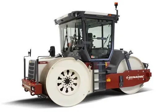
Source: Dynapac
Figure 110. Static Steel Roller
The contact pressure from the roller is the main source of compactive energy with steel rollers. Contact pressure is affected by the weight of the roller, typically 3–14 tons (2.7–12.7 t), and their drum width, typically 40–54 inches (102–137 cm). Static rollers usually can be ballasted to increase their mass. Water is commonly used for this purpose. Use of an appropriate antifreeze should be included if freezing is possible.
The weight of the roller is transmitted to the mixture through the contact pressure that is exerted under the drums. Therefore, the contact pressure under the drums should not exceed the supporting capability of the mixture being compacted. Harsher, more stable mixtures used on high-volume highways or airfields may require heavier rollers. Less stable mixtures used for driveways, parking lots, and other low-volume situations may require smaller, lighter rollers. In most cases, the asphalt mat is stable enough to allow the use of rollers with a high contact force.
Because steel-wheel rollers vary in width and weight, a simple calculation can be used to quantify the compactive effort applied by static rollers. By dividing the weight of the roller by the width of all drums, the overall static linear load can be determined, expressed in pounds per linear inch (PLI) or kilograms per centimeter (kg/cm) of roller. For example, an 8-ton roller with two 50-inch drum widths would calculate out to 160 PLI. The PLI can be used to match rollers of different sizes and manufacturers when establishing a rolling pattern. Static, steel double-drum rollers typically provide a minimum of 250 PLI (44.6 kg/cm), and large, three-wheel static rollers typically provide a minimum of 350 PLI (62.5 kg/cm), making them effective breakdown or intermediate rollers.
The two ways to adjust the compactive force of a steel-wheel roller are to adjust the ballast (weight) of the roller and the speed. Adding weight, or ballast, will apply greater force on the uncompacted mixture with each pass. Adjusting the speed affects the dwell time at each location on the mat. Slower rolling speeds raise the dwell time and increase the density increase from each pass of the roller.
All steel-wheel rollers (static and vibratory) used for rolling include a water-spray system and scrapers to moisten the drums to help prevent mix from sticking to the drums. Each drum should be checked for wear on the surface with a metal straightedge and should not be used if grooves or pits have worn into the rolling drum. Also, scrapers should be routinely inspected and replaced if they are excessively worn.
8.3.2 Pneumatic Tire Rollers
Pneumatic rollers (see Figure 111), commonly referred to as rubber-tire rollers, are equipped with rubber tires instead of steel drums. Typically, rubber-tire rollers are equipped with three to five tires on the front axle and four to six tires on the rear axle. The wheels can move up and down semi-independently of each other. Unlike a steel-wheel roller, the surface of a rubber-tire roller adjusts to the shape of the underlying surface. The intermediate position is the most common phase where pneumatic rollers are used.
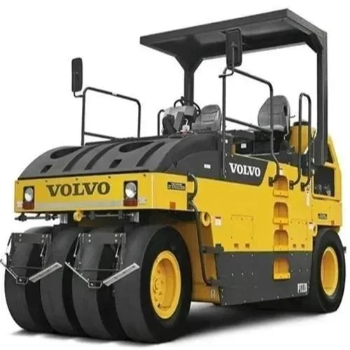
Source: Volvo
Figure 111. Pneumatic Roller
The oscillating wheels and conforming rubber tires result in a constant pressure being exerted across all points of the new mat and a kneading action that manipulates and compacts the mixture differently than a steel-wheel roller. Figure 112 illustrates the kneading action of a rubber-tire roller. The arrows illustrate typical lines of force in the mat.
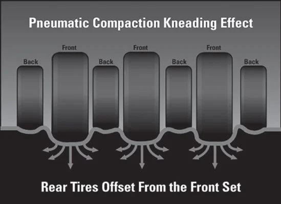
Source: Asphalt Institute
Figure 112. Forces of Pneumatic (Rubber) Tire Roller
Rubber-tire rollers work well on uneven surfaces, such as leveling courses, as the tires exert a constant pressure and do not bridge over low spots as do the steel-drum rollers. Their kneading action tends to tighten and densify the surface more than steel-drum rollers, thus decreasing permeability. Pneumatic rollers can provide increased density. They tend to be more effective in compacting tender mixes. On tender mixes, their tire air pressure may have to be reduced.
Rubber-tire rollers may be equipped with 15-, 17-, 20-, or 24-inch (380-, 430-, 510-, or 610- mm) diameter wheels and should have smooth tires for asphalt compaction. All the tires should have the same ply rating and the same inflation pressure, preferably the same model from the same manufacturer.
The contact pressure of the tires is calculated as the wheel load divided by the contact area of the tire with the pavement surface. The ply rating of the tire determines the maximum and minimum inflation pressures. Inflation pressure directly affects the contact area and resulting contact pressure. Running the tires at the mid to lower end of the inflation pressure range will help improve the surface texture by sealing the surface. Running the tire inflation pressure higher increases the compactive effort of the roller. Some pneumatic rollers have the capability to change tire pressure and automatically maintain a preset tire pressure while in operation.
There are several ways to adjust the compactive force of a rubber-tire roller. The first is to add or remove ballast. The second is to adjust the tire pressure. The third is to adjust the speed, which affects the dwell time just as in steel-wheel rollers. As was true for static steel rollers, slower speeds increase the compactive effort of each pass.
Pneumatic rollers can be used in the breakdown phase of compaction, but it is the intermediate phase where they see the most usage. Nonuniform subgrade strength can be more evident when rubber-tire rollers are used for breakdown, as the individual wheels can exert high stress on small areas of subgrade weakness that wide, rigid steel drums tend to bridge.
When a rubber-tire roller is used for breakdown rolling, very little horizontal movement of the mixture should occur in the direction of travel. This is because each tire flattens slightly as it drives over the mixture, permitting almost all the compactive force to be exerted vertically on the mat. Excessive horizontal movement of the mix in the direction of travel occurs when the tire diameter is too small, tires are overinflated, or the mix is not stable enough to use a rubber-tire roller for breakdown.
There is some lateral horizontal movement of the mix under a rubber-tire roller, at right angles to the direction of travel. This may cause small bumps or tire marks on the surface that can be rolled out with subsequent passes. Reducing the tire pressure will reduce this lateral displacement. The surface may look irregular, but this appearance is mostly cosmetic.
Desirable rubber-tire roller requirements for breakdown and intermediate compaction are as follows:
- Weight per wheel of 3,000 to 4,500 lbs (1,360 to 2,141 kg).
- A 20-inch (510-mm) minimum wheel diameter.
- Tire inflation pressure of 70 to 75 psi (483 to 517 kPa) when cold and 90 psi (620 kPa) when hot for most mixtures, but the pressure can be reduced if necessary for lower stability or tender mixtures.
Mixture pickup by pneumatic rollers needs to be addressed. Modified mixtures are the most prone to pickup. Preventing or at least reducing the amount of mix pickup by the rubber-tire roller is important. Keeping the tires clean and hot, near mat temperature, is the best way to avoid pickup.
Newer rubber-tire rollers are equipped with a water-spray system that can be used during initial warmup to mitigate mix pickup. Typically, each tire is equipped with a wetting mat that helps distribute the spray water over the tire surface. If pickup occurs, adding small doses of non-foaming detergent or approved water-soluble release agent to the roller water tank may help. All rubber-tire rollers are also equipped with scrapers to remove any materials from tires. Figure 113 illustrates such a system.
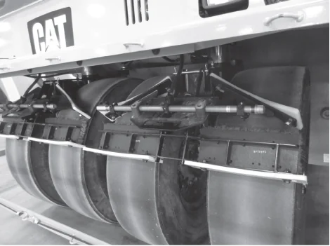
Source: Caterpillar, Inc.
Figure 113. Water-Spray System and Wetting Mats on Pneumatic Tires
The operator should strive to get the tires hot and keep them that way before initiating compaction. After ensuring that the wheels are clean, they should run the roller back and forth on a previously placed mat for at least 10 min to warm the tires. Using skirts that surround the tires is encouraged as this will help with both the warming process and keeping the tires warm. If an extended pause in paving occurs, the operator should keep the tires warm by keeping the roller moving as was done during the warmup time.
8.3.3 Vibratory Rollers
Vibratory rollers are the most versatile and common type of rollers used on asphalt. They come in a large variety of configurations. The rollers compact by a combination of weight and vibration of their steel drums. The vibration is produced by a rotating eccentric weight located inside the drum (or drums) and can be adjusted for both amplitude and frequency. These adjustments help to tailor the roller to the mix being paved and its thickness.
Vibratory rollers are the most versatile and common type of rollers used on asphalt.
Source: Dynapac
Figure 114. Double-Drum Vibratory Roller
There are two basic models of vibratory rollers: the single drum and the double drum. Typically, single-drum vibratory rollers are used to compact soil or aggregate bases, while double-drum vibratory rollers (shown in Figure 114) are used to compact asphalt. Both drums usually provide propulsion and vary from 3 to 5 ft (0.9 to 1.5 m) in diameter and from 4 to 7 ft (1.2 to 2.1 m) in width.
Static weight, as the term implies, is merely the overall weight of a vibratory roller operating in a static or non-vibratory mode. Vibratory rollers vary in static weight from 2.5 to 18 tons (2.3 to 16.4 t). Widths vary from 40 to 84 inches (102 to 214 cm). Their static weight in terms of drum width is generally from 160 to 180 PLI (29 to 32 kg/cm).
Frequency is the rate at which the vibration impacts generated by rotating eccentric weights occur. Frequency is expressed in vibrations per minute (VPM) or hertz (Hz). Typical frequencies of rollers used for asphalt compaction range from 2,500 to over 4,000 VPM (42 to 67 Hz). The high-frequency drum movement puts the aggregate particles in the mixture in motion, allowing them to slide past one another more easily under the compactive force of the drum. The general rule of thumb is to use the highest frequency setting available. High frequency allows the roller to be operated at a greater efficiency for any forward speed compared to lower frequencies.
Most vibratory rollers are equipped with a VPM indicator or gauge on the control panel that is visible to the operator. With wear and the extreme environment, these gauges can very quickly become out of calibration and inaccurate. A digital or vibratory handheld reed tachometer is a good QC tool that can be placed on the asphalt mat adjacent to the vibratory roller to accurately measure the VPM.
Amplitude is the up-and-down motion of the drum that is caused as the eccentric weight spins inside it. The positioning of weights is adjustable and can be spaced uniformly around the axle or entirely on one side. When the weights are uniformly spaced, they are essentially in balance and impart very little centrifugal force to the drum. Repositioning and locking the weights on one side of the axle unbalances the centrifugal force applied to the drum. This unbalanced condition imparts an up-and-down force to the drum that creates an impact force. The higher the amplitude, the greater the vertical force and the greater the impact force exerted on the mix.
While some vibratory rollers may have high and low amplitude settings, newer rollers provide the operator with a range of amplitude settings. Generally, the thickness of the mat, mix aggregate properties, and compactibility of the mixture are all factors to be considered when selecting the proper amplitude setting for a project. It is usually recommended to start with a high frequency and low amplitude and adjust from these settings as needed. As lifts get thicker, around 2.5 inches (65 mm) or more, or with more robust mixtures, then higher amplitude may be warranted at startup. Thin-lift applications that are less than 1 inch (25 mm) in compacted thickness are generally compacted with static rollers or vibratory rollers in static mode.
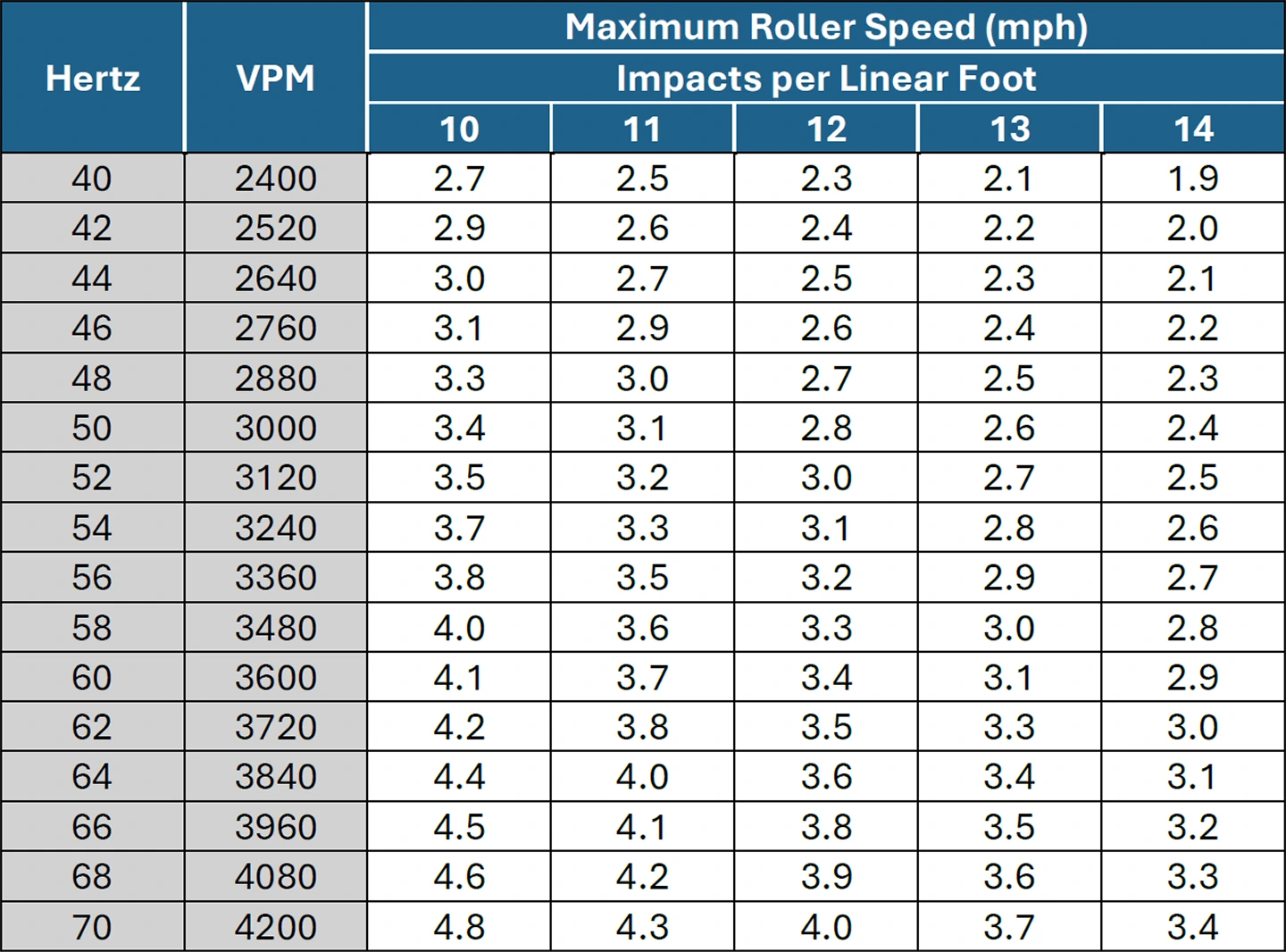
The number of impacts per foot or meter should be established as a target before compaction begins. This target should never be less than 10 impacts per foot (IPF) (31 impacts per meter). Corrugations or washboarding will result from fewer impacts than this minimum. The typical target range is 10–14 IPF (31–47 impacts per meter).
Modern rollers provide real-time feedback to the operator on amplitude, frequency, and IPF. If a roller does not have this feature, then the desired IPF can be used to calculate the appropriate forward speed manually to achieve the target. For example, if the minimum desired IPF is 12, and the roller’s frequency is 3,600 VPM, the maximum speed of the roller in terms of miles per hour (mph) is calculated as follows:
3,600 VPM / minimum 12 IPF = maximum 300 ft per min, or maximum 3.4 mph
Building a chart such as shown in Table 9 allows an operator to easily see what speed they need to target to achieve the appropriate impact rate. Caution is encouraged when speeds increase even on high-frequency rollers. Their higher frequency advantages are maximized when traditional speeds are targeted.
Table 9. Maximum Roller Speed Versus Drum Frequency (for range of 10 to 14 IPF)
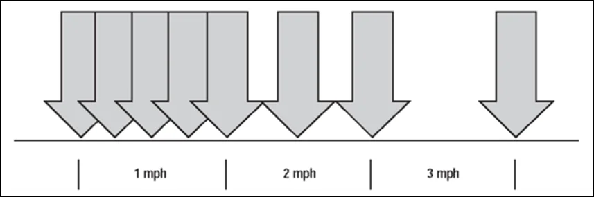
In summary, impact spacing, vibration, amplitude, and roller speed can be used to adjust the compactive effort of a vibratory roller. Slowing the forward speed of the roller decreases the impact spacing, causing the number of IPF to increase. As the speed of the roller increases for a given vibration frequency, the spacing of the impacts grows. The relationship between speed and frequency to obtain a target IPF is illustrated in Figure 115. For asphalt mix compaction, rollers are generally operated at the highest frequency setting available for that roller, with the speed of the roller adjusted to meet the desired impact spacing.
Source: Asphalt Institute
Figure 115. Relationship Between Speed and Vibration Frequency
Vibratory rollers can be operated with both drums, either the front or the back drum, or neither drum vibrating. Each of these options has a situation where it may be preferred. With both drums vibrating, the maximum compactive effort per pass is occurring. This may be used on a stable mixture that requires the most energy to achieve the desired density. Having only the front drum vibrating has the front drum achieving density and the rear drum creating a smoother finish. Switching it up and having the trailing drum vibrating may be a wise choice for a mixture with less stability or more tenderness. Operating in static mode for both drums is usually for thin lifts or when in finishing mode.
Paying attention to the feedback that a mixture provides during compaction can assist in the densification of the pavement, especially with vibratory rollers. For example, a tender mix may respond well to a pass or two in static mode followed by vibrations being initiated to achieve the desired density. However, if conditions change and the mix starts to cool more quickly, the excessive energy used may crush aggregate or de-compact the mixture.
Special attention may be necessary when using a vibratory roller on steep grades. Especially on the initial passes, care should be taken when the roller is traveling downhill to not vibrate and shove the mix down the slope.
8.3.4 Oscillatory Rollers
Oscillatory rollers (see Figure 116) have a longer history in Europe, where they were developed, but they are now common tools in the Western Hemisphere too. They are double-drum steel rollers that look very similar to vibratory rollers. An oscillatory roller will typically have an oscillatory and a vibratory drum; some have oscillation on both drums. They are usually used effectively in either the breakdown or intermediate phase. Instead of a mostly vertical compactive force as generated by vibratory rollers, oscillatory rollers are equipped with two vibrating units that operate in synchronization to create a rocking motion in the drum. This rocking motion provides both horizontal and vertical compactive forces that are transmitted tangentially into the asphalt mat.
Source: Wirtgen
Figure 116. Double Drum Oscillatory Roller
Oscillatory rollers exert lower vertical impact forces than vibratory rollers, which may be desirable where there are concerns of damaging nearby infrastructure. Some examples are bridge decks or where underground utilities, especially older ones, are not very deep. Using an oscillatory roller to compact a longitudinal joint can also be very effective. The less aggressive kneading action from an oscillatory roller has been shown to achieve high-density readings with less potential for any tearing of the mat. Moreover, when a mixture is struggling to respond favorably to vibratory rollers, or at lower mixture temperatures, an oscillatory roller may be effective.
8.3.5 Combination Roller
Combination rollers have two different roller types (static steel-wheeled or vibratory steel-wheeled and pneumatic [rubber-tired]) on the same roller (see Figure 117). The most common type of combination roller is equipped with a vibratory drum on the front and pneumatic rubber-tired rollers on the back. This configuration combines the benefits of a vibratory steel drum with the kneading action of pneumatic tires. They are generally used on smaller paving projects such as parking lots, projects with uneven surfaces (manholes, catch basins, etc.), and projects with steep grades. Some contractors also find them to be useful for the compaction of approaches where their maneuverability can be advantageous.
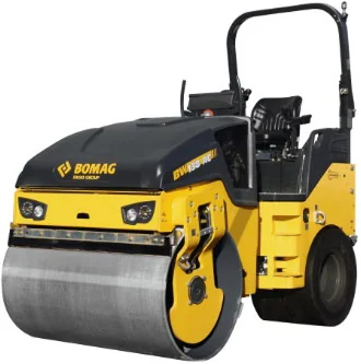
Source: Bomag
Figure 117. Combination Roller
8.3.6 Vibratory Pneumatic Roller
Vibratory rubber-tired rollers, as shown in Figure 118, are pneumatic rollers that have the capability to vibrate the front tires. As is the case with steel-drum vibratory rollers, vibrations are generated by a rotating eccentric weight on shafts along the front axle. Both the frequency and amplitude of the vibrations are controlled independently of roller travel and engine speed. This type of roller provides the benefits of both the kneading action from the rubber tires with the dynamic forces from vibratory compaction. This roller configuration is especially beneficial for intermediate rolling and compacting along confined joints.
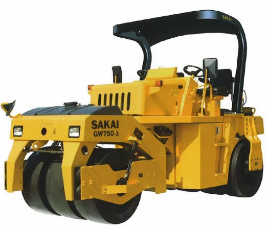
Source: Sakai America, Inc.
Figure 118. Vibratory Pneumatic Rubber-Tired Roller
8.3.7 Intelligent Compaction
Intelligent compaction (IC) is a compaction process that utilizes advanced technology to produce a more consistently densified product. An example of an IC system is shown in Figure 119. An IC roller is a vibratory roller with technology designed to provide better QC during the compaction process. IC rollers incorporate an integrated system to measure stiffness, Global Positioning System (GPS)-based real-time mapping, infrared temperature sensors (front and back), and onboard computers. The computer monitor displays color-coded maps in real time to track roller location, number of passes, surface temperatures, and relative stiffness of compacted materials. The GPS provides extremely accurate roller location data during the compaction process that can be paired with mat temperature and accelerometer data. Roller drums are equipped with accelerometers to measure drum movement during compaction and translate this into an Intelligent Compaction Measurement Value (ICMV). ICMV is a generic term coined by FHWA. It is a real-time measurement of the mixture’s relative stiffness. Five levels of ICMV are currently envisioned, from a relatively basic empirical solution to a mechanistic solution based on dynamic methods and artificial intelligence.
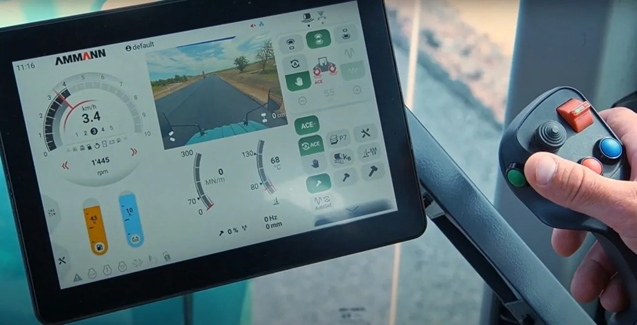
Source: Ammann Group
Figure 119. Roller Equipped with IC Technology
The computer monitor showing a color-coded project map is mounted so the operator can see the ICMV, the mat temperature, and the number of roller passes made during the compaction process. Research and field experience have shown that IC technology will improve the consistency of roller passes and uniformity of compaction simply by providing this critical information in real time to the operator and other project personnel. Figure 120 shows a conventional double-drum vibratory roller equipped with IC technology.
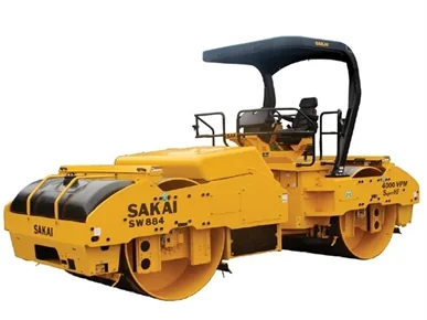
Source: Sakai America, Inc.
Figure 120. Double-Drum Vibratory Roller Equipped with IC Technology