
AAPTP
  • Small
  • Medium
  • Large
  • Small
  • Medium
  • Large
  • Home
  • Handbook
    • Asphalt Paving Handbook
    • Videos
    • Figures
    • Tables
  • Checklists
  • Abbreviations
  • About
  • HOME
  • Handbook
    • Asphalt Paving Handbook
    • Videos
    • Figures
    • Tables
  • CHECKLISTS
  • ABBREVIATIONS
  • About
1. Introduction
  • 1.1 Handbook Purpose and Organization
  • 1.2 Airfield Paving
  • 1.3 Asphalt Mixtures Defined and Classified
  • 1.4 Workmanship
  • 1.5 Certification and Accreditation Programs
2. Project Organization
  • 2.1 Introduction
  • 2.2 Project Documents
  • 2.3 Preconstruction Conference
  • 2.4 Ongoing Communication
  • 2.5 Ongoing Records
  • 2.6 Safety
3. Asphalt Materials and Mix Design
  • 3.1 Introduction
  • 3.2 Asphalt Binder: Grading Systems And Properties
  • 3.3 Aggregate Characteristics And Properties
  • 3.4 Mixture Volumetrics
  • 3.5 Asphalt Mix Properties
  • 3.6 Additives
  • 3.7 Mix Design Procedures
  • 3.8 Laboratory Versus Plan-produced Mixes
  • 3.9 Summary
4. Mix Production
  • 4.1 Introduction
  • 4.2 Material Storage and Handling
  • 4.3 Aggregate Cold Feed
  • 4.4 Aggregate Drying and Heating
  • 4.5 Batch Plants
  • 4.6 Drum and Continuous Plants
  • 4.7 Emission-Control System
  • 4.8 Temporary Mixture Storage
  • 4.9 Weighing and Loadout
  • 4.10 Safety
  • 4.11 Troubleshooting and Checklists
5. Surface Preparation
  • 5.1 Introduction
  • 5.2 Base Preparation for New Asphalt Pavements
  • 5.3 Asphalt Surface Preparation for Asphalt Overlays
  • 5.4 PCC Surface Preparation For Asphalt Overlays
  • 5.5 Tack Coat
  • 5.6 Summary
6. Mixture Delivery
  • 6.1 Introduction
  • 6.2 Planning
  • 6.3 Truck Types
  • 6.4 Proper Truck Loading
  • 6.5 Hauling Procedures
  • 6.6 Unloading the Mix
  • 6.7 Tracking Quantities
7. Mix Placement
  • 7.1 Introduction
  • 7.2 Tractor Unit
  • 7.3 Screed Unit
  • 7.4 Grade Control
  • 7.5 Layer Thickness
  • 7.6 Establishing Paver Speed
  • 7.7 Related Paving Operations
  • 7.8 Best Practices Checklists
8. Compaction
  • 8.1 Introduction
  • 8.2 Definitions
  • 8.3 Rollers
  • 8.4 Factors Affecting Compaction
  • 8.5 Compaction Variables Under The Operator’s Control
  • 8.6 Determination of Rolling Pattern
  • 8.7 Roller Checklists
9. Joint Construction
  • 9.1 Introduction
  • 9.2 Transverse/Construction Joints
  • 9.3 Longitudinal Joints
  • 9.4 Echelon Paving and Rolling
  • 9.5 Unconventional Longitudinal Joint Methods
10. Segregation
  • 10.1 Introduction
  • 10.2 Recognizing Physical Segregation, Causes, and Solutions
  • 10.3 Four Stages Where Segregation Can Originate
  • 10.4 Thermal Segregation
  • 10.5 Confirming and Quantifying Segregation
11. Quality Assurance
  • 11.1 Introduction
  • 11.2 Definitions
  • 11.3 General Types Of Specifications
  • 11.4 Quality Control Plan
  • 11.5 Sampling Methods
  • 11.6 Quality Control At The Plant
  • 11.7 Quality Control In The Field: Placement And Compaction
  • 11.8 Acceptance
12. Mat Problems
  • 12. Mat Problems
  • 12.1 Surface Waves
  • 12.2 Tearing (Streaks)
  • 12.3 Nonuniform Texture
  • 12.4 Screed Marks
  • 12.5 Screed Responsiveness
  • 12.6 Surface (Auger) Shadows
  • 12.7 Poor Precompaction
  • 12.8 Joint Problems
  • 12.9 Checking
  • 12.10 Shoving And Rutting
  • 12.11 Bleeding And Fat Spots
  • 12.12 Roller Marks
  • 12.13 Poor Mix Compaction
  • 12.14 Other Pavement Problems
Appendix
  • AAPTP Airport Asphalt Videos

9. Joint Construction

9.4 Echelon Paving and Rolling

Youtube Video Icon

Watch Video

Echelon Paving

Because LJs are often susceptible to early deterioration, it is wise to reduce the number of LJs on a project where possible. If project staging and traffic control allow paving multiple lanes or shoulders in a single pass with screed extensions, at least one joint can be eliminated. Section 7.3 covered screeds and screed extensions, including photos.

Another excellent option to reduce the number of LJs is to utilize echelon paving if project staging, logistics, and traffic control allow. In echelon paving, adjacent lanes are placed and compacted side by side at the same time with multiple paving trains. The LJ created between these paving trains is called a hot joint because both sides are hot when placed and compacted. Experience has found that hot joints from echelon paving have better long-term performance compared to cold joints.

Experience has found that hot joints from echelon paving have better long-term performance compared to cold joints.

Echelon paving is not common on roadway projects because there is typically a need to maintain traffic flow, so closing multiple lanes is difficult. Airfields, large commercial parking lots, and new highway construction are examples where echelon paving should be considered (see Figure 146).
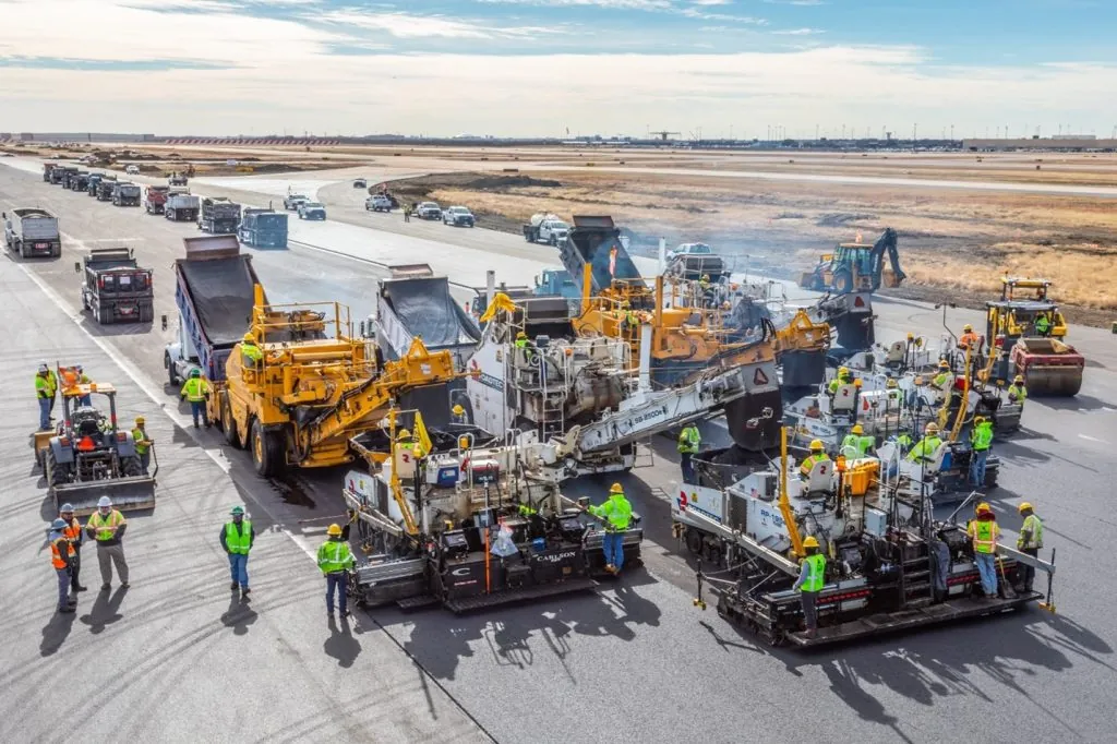
Figure 146. Echelon Paving with Four Paving Trains on a Runway at DFW Airport

Source: Dallas Fort Worth International Airport
Figure 146. Echelon Paving with Four Paving Trains on a Runway at DFW Airport

The limiting factor on the number of paving trains utilized with echelon paving is often the overall mix production to feed the pavers. Utilizing two paving trains is the most common occurrence with echelon paving, while utilizing four paving trains, as seen in Figure 146, is extremely rare.

Lanes are placed simultaneously with the pavers separated by only a short distance, usually less than 100 ft (30 m). This short distance allows the mats to effectively be welded together by the compaction train before the mix on either side of the joint cools. Overlap is typically targeted at 1 inch (25 mm).

Having a standard rolling train behind each paver is recommended. To maximize density at the hot joint, the breakdown roller following the lead paver should leave approximately 4 to 6 inches (100 to 150 mm) of the common edge or joint unrolled. This common joint is then compacted by the first pass of the breakdown roller following the second paver. To accomplish this effectively, the second paver must keep as close as possible to the first paver to minimize any temperature difference between each side of the joint. The material on each side becomes a single mass under the roller, and there is little or no difference in density between the two lanes.

Previous Section
Next Section

© National Asphalt Pavement Association (NAPA). All rights reserved|Privacy Policy

6406 Ivy Lane, Suite 350 Greenbelt, Maryland 20770-1441

|888-468-6499
Information

There are no items associated with the selected chapter.