12. Mat Problems
12.11 Bleeding And Fat Spots
12.11.1 Description
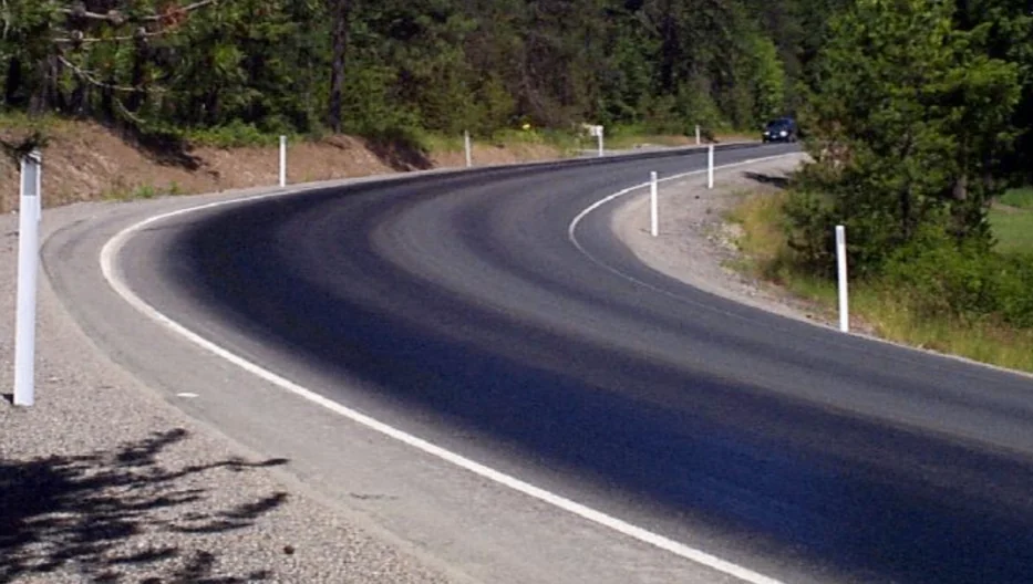
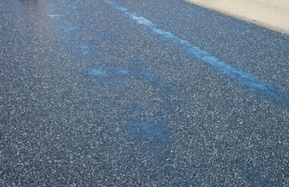
Bleeding of an asphalt mixture (see Figure 171) occurs when the asphalt binder flows to the top of the mix surface under the action of traffic loading. Bleeding is often seen as two flushed longitudinal streaks in the wheel paths of the roadway. Fat spots in an asphalt mixture (see Figure 172) are isolated areas where asphalt binder has come to the surface of the mix during the laydown and compaction operation or later under traffic. These spots can occur erratically and irregularly, or they may be numerous and in a fairly regular pattern.
Source: Pavement Interactive
Figure 171. Asphalt Bleeding in the Travel Lane
12.11.2 Causes
Fat spots are caused primarily by excessive moisture in the mix (see Chapter 3). The problem is more common with mixtures that contain a high percentage of fine aggregate (oversanded mixes) and those that contain aggregates with a high porosity. If all the moisture in the coarse and fine aggregate is not removed during the drying and mixing operation at the asphalt plant, the moisture vapor will force asphalt binder to the surface of the mix behind the paver as the moisture escapes from the mix and evaporates. Fat spots occur more frequently when aggregate stockpiles are wet or when the moisture content varies in different portions of the stockpiles.
Fat spots are caused primarily by excessive moisture in the mix. The problem is more common with mixtures that contain a high percentage of fine aggregate (oversanded mixes) and those that contain aggregates with a high porosity.
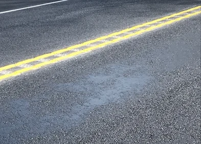
Fat spots sometimes occur in areas where petroleum products, such as oil or diesel fuel, were spilled onto the pavement surface prior to overlay (see Figure 173 and Figure 172) or have contaminated the mix. Use of petroleum-based release agents in the mix haul vehicles can also cause fat spots in the asphalt mix (see Section 6.5.1). In addition, fat spots can be associated with segregated areas in the mix (see Chapter 10). If the mix deposited on the roadway by the paver is segregated, areas in which excess asphalt binder is present in the mix can result in free binder material on the top of the layer being placed.
The causes of bleeding normally fall into two categories. The first is an excess of fluids in the asphalt mixture—either asphalt binder or moisture or both. Under traffic, the extra moisture and asphalt binder will be pulled to the surface by the passage of vehicle tires. This bleeding phenomenon usually occurs on new mix and during hot weather when the viscosity of the asphalt binder is at its lowest level. Typically, the bleeding occurs shortly after traffic is allowed to travel over the fresh mix—while there is still some moisture in the mix and while the viscosity of the asphalt binder is still relatively low.
The causes of bleeding normally fall into two categories: an excess of fluids in the asphalt mixture or a lack of adequate space in the mix for the asphalt binder.
Source: Pavement Interactive
Figure 172. Fat Spot Caused by Localized Excess Asphalt
Source: Asphalt Institute
Figure 173. Fat Spot Caused by Fuel Oil Spill Prior to Overlay Construction
Bleeding may also be associated with a lack of adequate space in the mix for the asphalt binder. If the VMA content and air void content of the mix do not provide enough room for the binder material, bleeding can occur as the mix is densified by traffic, both shortly after construction and later. The traffic compaction process will decrease the air void content of the mix and may, in turn, squeeze some of the asphalt binder out of the mix. The “extra” asphalt will appear as a longitudinal streak or fat spot throughout the length of each wheel path.
One additional possible cause of bleeding is the condition of the pavement layer on which the new mix is placed. If the underlying layer has excess asphalt on its surface or excess crack seal material in the cracks and joints, some of this material may be drawn up through a thin new mix layer. Further, if too much tack coat is applied to the original pavement layer, the excess material may be pulled up through a thin overlay and contribute to the bleeding problem. However, neither of these two causes is common.
12.11.3 Solutions
Variations in the asphalt mix temperature behind the paver indicate that the moisture content of the mix may also be variable. Where moisture has evaporated, the temperature is lower. This latter phenomenon can contribute to both the bleeding of the mix later under traffic and the generation of fat spots in the mix during construction. It is important, therefore, that the aggregate used in the mix be relatively dry and that the moisture content of the mix upon discharge from the asphalt plant be as low as possible, but not more than 0.5 percent. Extra care needs to be taken in drying when producing mixtures that incorporate highly absorptive aggregate.
Bleeding problems caused by excess asphalt binder in the mix can most easily be solved by reducing the binder content, consistent with other properties of the mix, such as air voids, VMA, and strength or stability. Bleeding problems that occur in conjunction with pavement rutting usually can be solved, however, only by a complete redesign of the mixture, with emphasis on proper air void content and VMA criteria.
12.11.4 Effects on Performance
Occasional fat spots in the mix should not affect the ultimate durability of the pavement to a significant degree. The presence of many fat spots, or significant amounts of bleeding in the wheel paths, does affect pavement performance, however, because of variable binder and air void content in different parts of the mix. In addition, other mix problems, such as shoving, rutting, and loss of skid resistance, may occur in a mix that contains many fat areas or areas of bleeding in the wheel paths. The design of the mixture, the operation of the asphalt plant (more complete removal of moisture), or both should be checked to ensure that the mix produced will provide adequate pavement performance under vehicular loading.