7. Mix Placement
7.4 Grade Control
The goal of the grade control system is to maintain the screed tow points on a smooth line of pull as the paver travels forward. The self-leveling action of the screed takes place continuously as the tractor unit travels over the roadway. The thickness of the asphalt mat being placed is determined by the reaction of the screed to the location of the tow points, the speed of the tractor, and the head of material in the auger chamber. The entire operation occurs without the thickness-control cranks on the screed ever being changed.
7.4.1 Manual Grade Control
It is easy to visualize that if a paver were a single axle unit with the tow points fixed to the axle, the tow point elevation would directly follow the existing surface, with minimal improvement to the final surface smoothness. Because pavers have multiple axles, with the tow points being roughly in the middle of the paver’s wheelbase, the length of the paver wheelbase becomes the reference. Thus, based on the combination of the tow point movement being the average of the wheelbase and the delayed screed reaction, under manual screed control the screed will average out deviations in the roughness by placing more mix over the low points and less mix over the high points of the existing surface.
7.4.2 Automatic Grade Control
Automatic grade controls enable the tow point to refer to a reference system that is not directly tied to the movement of the tractor unit but to a reference line established by a mobile ski, preset stringline, or remote (three-dimensional [3-D]) control. Automatic grade controls adjust the tow points up or down to maintain a constant height difference between the tow point and the reference line. Keeping the elevation of the tow points constant in direct relationship to the reference permits the screed to maintain a more consistent angle of attack, which in turn provides for a smoother mat behind the screed.
Many factors affect the smoothness of the mix placed by the paver. The use of automatic screed controls by itself does not ensure that the mat constructed will be smooth. Proper attention to the operation of the paver, as discussed in Section 7.3, is extremely important to obtaining a smooth-riding pavement layer. In addition, it is important to remember that because the free-floating screed places more mix in low spots and less mix on high spots, differential compaction of the asphalt mix will result in a compacted surface that is rougher than the surface placed.
It is important to remember that because the free-floating screed places more mix in low spots and less mix on high spots, differential compaction of the asphalt mix will result in a compacted surface that is rougher than the surface placed.
7.4.2.1 Mobile References
There are several types of mobile references (sometimes referred to as a “ski”). The purpose of a mobile reference system is to average the effects of grade changes in an existing surface over a greater distance than that obtained from just the wheelbase of the paver.
7.4.2.2 Floating-Beam Grade Reference
A floating-beam mobile reference is the most common grade reference system (see Figure 101). It consists of a rigid beam with a series of spring-loaded feet attached to the bottom of the beam. One or more of the feet can move over a single high or low point on the pavement surface without altering the overall slope of the beam along its length. The hinged “feet” can “walk” over small undulations or loose rock on the roadway without altering the slope of the beam. The floating-beam reference system will average the variation of the existing grade over 30–40 ft (9–12 m).
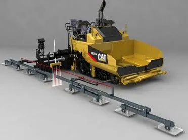
Source: Caterpillar Inc.
Figure 101. Floating-Beam Grade Reference
7.4.2.3 Sonic-Tracker Grade Reference
A sonic-tracker mobile reference system attaches a rigid beam to the side of the paver that holds multiple sonic sensors along its length (see Figure 102). The sensors direct sonic waves downward that echo off the surface. The echo is timed to establish the height of the sensor above the reference surface. The multiple height readings are continuously averaged together to provide a reference line.
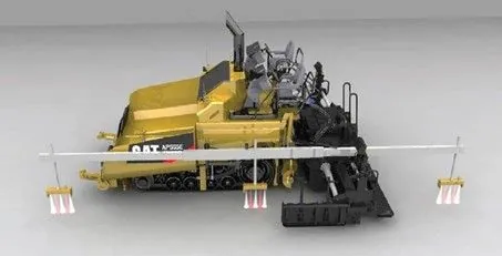
Source: Caterpillar Inc.
Figure 102. Sonic-Tracker Grade Reference
7.4.2.4 Combination Grade References
The longer the grade reference used, the better the paver will average out variations in the existing pavement surface. Consequently, the smoothest pavements are built using a combination over-the-screed mobile reference system that senses off the existing grade in front of the paver and reaches over-the-screed to sense off the new mat being placed behind the screed (see Figure 103). Since the new mat is significantly smoother than the existing pavement surface, the majority of the variations detected are limited to those measured by the front sensor(s). Combination systems can be made up of individual floating beams connected by either a rigid framework or spring-loaded wire stretched over the screed. This type of system can reach between 40 and 60 ft (12 to 18 m) in length.
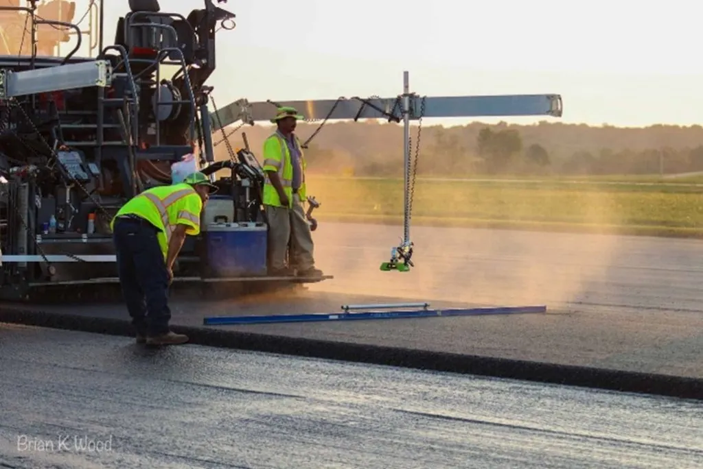
Source: Brian K. Wood
Figure 103. Over-the-Screed Grade Sensor and Cross-Slope Checking
7.4.2.5 Fixed-Grade References
A fixed-grade reference refers to a method of grade reference that duplicates an existing surface or profile-primarily a single point reference (matching shoe or non-contact sensor) or a fixed stringline reference. The purpose is to duplicate or mirror the respective reference.
7.4.2.6 Single-Point Reference (Matching Shoe)
surface, such as an adjoining lane, curb and gutter, or a lower surface layer. A single-point reference device may be a matching shoe or a single non-contact grade sensor.
Fixed-grade references using a single device should be used with caution because anomalies, such as mix spillage and pebbles or drainage inlets in curb and gutter, can create an irregular profile that will be directly reflected in the adjacent paving surface.
Fixed-grade references using a single device should be used with caution because anomalies, such as mix spillage and pebbles or drainage inlets in curb and gutter, can create an irregular profile that will be directly reflected in the adjacent paving surface.
The location where the single-point sensor is placed on the paver will impact the response of the paver to grade changes. It is important to remember that the sensor is calibrated to detect a specified reference or measure a distance. As a wand or matching shoe traverses a reference, the tow point will maintain a constant distance to within a very small tolerance. A non-contact sensor is constantly measuring a distance, and the tow point moves to stay within a very close tolerance to a predetermined distance. Both types of sensors, shown in Figure 104, will continuously call for the tow points to change until the offset with the sensor returns to its “comfort range.”
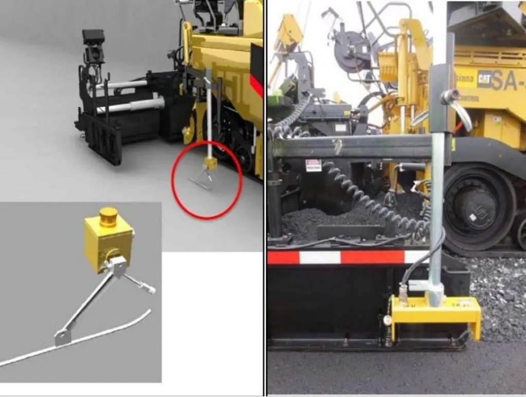
Source: Caterpillar, Inc.
Figure 104. Single Point Grade Referencing
Placement near the tow point locks in the distance between the grade reference and the tow point elevation. The sensor and tow point really do not care what the screed does as it trails one tow arm length behind the tow point. The fact that it takes the screed one tow arm length to get 65 percent of the angle of attack change reconciled will put the screed very close to where it should be as paving progresses. Placement of the single-point sensor at the tow point will result in smaller movements of the tow point and smoother pavement, but it may not always match the grade reference exactly.
When the sensor is placed at the rear of the tow arm, near the auger, the tow point reaction is quite different. When the sensor is mounted near the auger or screed, the sensor more closely follows the position of the screed. When the sensor gets out of its comfort range, it calls for an adjustment to the tow point elevation. But since the screed is slow to react to the tow point change, the sensor continues to call for more movement of the tow point; hence the tow point continues to move until the sensor is satisfied. These movements of the tow point height are larger and more rapid when compared to the tow point reaction with the sensor located at the tow point. The result is that the screed quickly reaches the new elevation called for by the sensor. Placement of a single point sensor near the auger will obtain the closest continuous match to the grade reference, but smoothness may be reduced.
When placing the second lane of a base course or a binder course layer, it may be better to use a longer mobile reference ski instead of a joint-matching shoe. The mobile reference will provide better input for constructing a smooth pavement surface than a single-point sensor. If sufficient smoothness has been achieved in lower layers, a single-point matching device would be an appropriate choice to match adjacent surfaces or specific elevation for the final lift.
7.4.2.7 Fixed Stringline
The use of an erected stringline, shown in Figure 105, provides the opportunity for the placement of the smoothest possible asphalt mat behind the paver screed. The stringline can be made of wire or nylon cord. This method of supplying elevation input provides the most consistent reference for the paver tow points, enabling a predetermined grade to be matched very accurately if the controls are used properly.
Source: Applied Research Associates, Inc. (ARA)
Figure 105. Stringline on an Airfield Project
Unfortunately, there are several obstacles to successful implementation of fixed stringline control. The most notable are that it is very expensive and time-consuming to install and maintain. In addition, the line must be kept very taut and undisturbed by personnel and equipment over long sections of the project. Thus, for the vast majority of highway paving projects, an erected stringline is not used.
However, fixed stringlines can be very helpful where longitudinal and transverse profiles along with final elevation points are important, such as airfields. Special projects such as racetracks or other applications with critical superelevated curves may be good candidates for fixed stringline grade references.
It is important to note that establishing a smooth paving platform contributes significantly to a uniform and balanced laydown operation. Using automatic controls on milling machines improves mixture yield, smoothness, and in-place density.
7.4.3 Slope Control
Paving that is done with automatic screed controls as described in Section 7.4.2 is often accomplished with a combination of grade control on one side of the paver and slope control to determine the grade on the other side of the machine. The slope control operates through a slope sensor that is located on a cross beam between the two side arms of the screed. The cross slope is regulated by a pendulum device that is part of the slope control system. The required degree of cross slope is simply dialed in to the slope controller, shown in Figure 106.
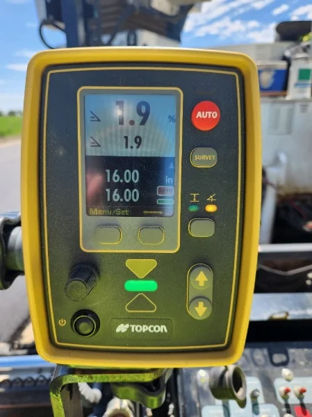
Source: Asphalt Institute
Figure 106. A Modern Cross Slope Controller
One side of the screed is controlled by the grade sensor(s), while the other is controlled by the slope controller. In almost every case, the inside or centerline edge of the finished mat is controlled by grade and the outside edge by slope. It is very difficult to match the centerline joint if slope control is used to control the inside edge of a paved lane. It is extremely difficult, if not impossible, on multiple-lane sections.
When slope control is used, the thickness of the mat on the side of the machine that is controlled by the slope sensor may be variable in depth, depending on the condition of the existing surface. Without regard to the condition of the existing surface, the slope controller maintains a constant cross slope of the finished mat exiting the paver, regardless of the resulting thickness of the asphalt layer placed. If there is a high point in the present pavement surface, the slope controller causes the screed to place less material over that location; if there is a low point in the existing pavement, the slope controller causes the screed to deposit more mix in that location. It is good practice to check the slope of the lane routinely with a carpenter level or other method.
When properly operated, a slope controller will very accurately place a lift with a surface at the exact slope. However, if the sublayer is irregular, differential compaction will result, and the final surface will not be uniform across the section after rolldown. A properly prepared or corrected base layer that conforms to the longitudinal and transverse profile will greatly enhance a uniform and balanced paving operation. For a wide pavement, such as an airport runway, it is good practice to continually check the elevation of the outside edge of the mix being placed. While the use of one or more stringlines across a wide pavement can help provide the proper cross slope, dual mobile reference skis (controlling both sides of the paver) are often utilized.
7.4.4 Remote Grade and Slope Control (3-D Paving)
Traditional grade and slope control is often referred to as two-dimensional (2-D) paving. Three-dimensional (3-D) paving allows a laydown operation to achieve a specific elevation while maintaining longitudinal grade and slope. Achieving an exact result requires control of the lower layers of the pavement section. Since the placement of nonuniform mat thickness results in differential rolldown, a successful project begins with a precise base layer placement or milling operation.
3-D paving is a process where the tow points of the paver are automatically controlled by an electronic file that contains all the grade, slope, and elevation data. This data can be from the original project design file or captured and recorded during project construction, for example, during subgrade preparation, base layer placement, or milling operations.
3-D paving begins with one or two prisms located on the screed, shown in Figure 107. These prisms are mounted at a fixed and measured height above the screed. The prisms are constantly tracked by an onsite universal total station.
Source: SITECH Construction Systems
Figure 107. Dual Receivers on a Paver
Depending on the project site, there may be multiple total stations because they must maintain line of sight with the paver and are limited in range to 500–1000 ft (150–300 m), depending on the system provider. Total stations (shown in Figure 108) constantly measure the location of the paver prism and transmit position data to a receiver and controller unit on the paver. The controller processes the position data received and controls the tow point height to maintain the screed at the final elevations in the data file.
Some systems, often called 3-D grade control, may use only one prism to control the grade line (replacing the ski) on one side of the screed, with the other end of the screed controlled by the slope controller or matching shoe. Other systems use two prisms, one on each side of the screed, to provide full 3-D control.
Total stations are located at control points throughout the project, with known coordinates and elevations pre-determined for each. 3-D paving is typically used on strategic projects with a limited footprint due to the limited range of the total stations. Excellent results can be expected on all types of projects but may become difficult to execute on long, high-tonnage overlay projects, whereas airfield projects are excellent candidates for 3-D paving.

Source: JP Excavating, Inc.
Figure 108. Universal Total Station Tracking Paver