7. Mix Placement
7.2 Tractor Unit
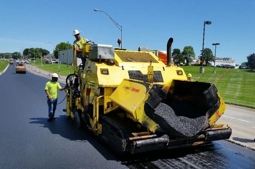
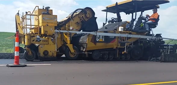
A paver has two primary components: the tractor unit and the screed unit. The tractor unit provides all electrical, hydraulic, and propulsion energy required to complete placement operations in the field. The tractor unit performs the functions necessary to receive asphalt mix from haul trucks or MTVs or to pick up mix with a windrow elevator, carry it through the machine back to the augers, and uniformly distribute the mix across the width of the screed. The tractor unit tows a self-leveling screed unit through the mix as it is placed. The screed provides the initial texture and compaction to the mat as it passes out from under the screed. Figure 79 shows key elements of the tractor and screed units.
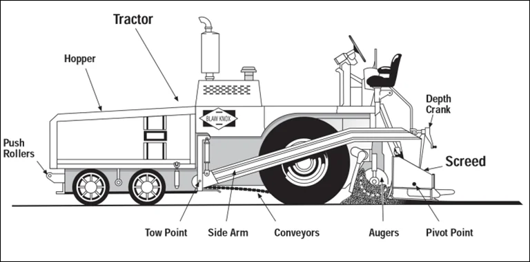
Source: Asphalt Institute
Figure 79. Schematic of Asphalt Paver
7.2.1 Push Rollers
The push rollers, located on the front of the paver hopper, are used to maintain contact with the tires of the haul truck and to push it ahead of the paver. The rollers must be clean and rotate freely to allow smooth forward travel of the paver. If the push rollers are not cleaned periodically and do not rotate freely, the truck tires will slide on the rollers and increase the load on the paver. Moreover, if one roller rotates freely and the other does not, the paver may be more difficult to steer.
Many pavers are equipped with a truck hitch located underneath or incorporated into the push rollers on the front of the paver, as shown in Figure 80. The purpose of the hitch is to keep the truck in contact with the paver and thereby prevent the truck from becoming disconnected and inadvertently dumping mix on the pavement in front of the paver. The hitch, which is controlled by the paver operator, has forward-extending arms with rollers attached. The rollers are retracted into the truck tire rim and against the tire itself, preventing the truck from losing contact with the paver during the unloading process. Once the truck bed has been emptied of mix, the truck hitch is withdrawn, and the truck is able to pull away from the paver.
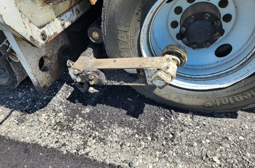
Source: Asphalt Institute
Figure 80. Truck Hitch on Front of Paver
7.2.2 Material Handling System
The material feed system on the tractor unit plays a very important part in producing a consistent, high-quality mat behind the paver. The material feed system typically consists of a paver hopper, slat conveyors, material flow gates, and a pair of augers.
7.2.2.1 Paver Hopper
The paver hopper, shown in Figure 81, receives delivered mix and serves as a temporary storage area for material delivered from the haul vehicle, the windrow elevator, or the MTV. The hopper capacity allows the paver to maintain a constant forward motion between loads of mixture being delivered. Mixture delivery methods are detailed in Chapter 6.
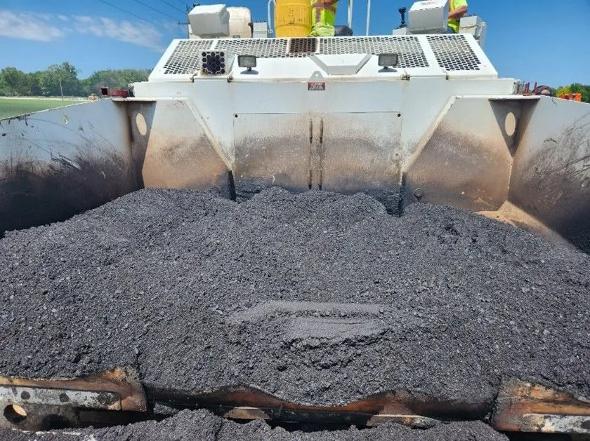
Source: Asphalt Institute
Figure 81. Paver Hopper Between Loads
7.2.2.2 Slat Conveyors
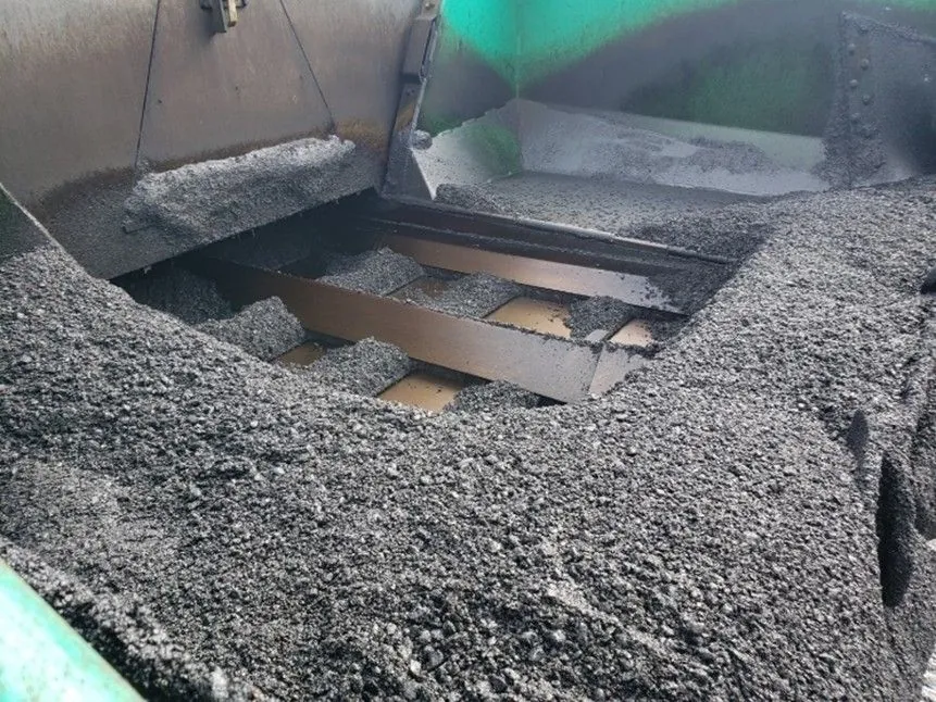
At the bottom of the paver hopper there is typically a set of slat conveyors consisting of heavy chains and flight bars (see Figure 82). The slat conveyors are a continuous system, with the slats being rotated back to the bottom of the hopper underneath the paver itself. These devices are used to carry the asphalt mix from the hopper through the tunnels on the paver and back to the augers. The slat conveyor on one side of the paver operates independently from the one on the other side. The conveyor system operates independently of the speed of the paver and, on most pavers, independent of the speed of the augers. Thus, the amount of mix being carried back through the paver on one side may differ from that being delivered on the other side, and the paver operator can change the feed rate to either side of the paver to pave shoulders, ramps, turnouts, etc.
On some pavers, the slat conveyor system has been replaced by a screw conveyor system. The purpose of this latter system is to remix the mix in the paver hopper and reduce segregation behind the screed.
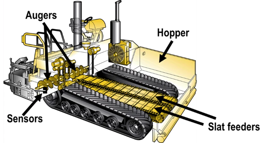
Source: Asphalt Institute
Figure 82. Material Feed System
7.2.2.3 Flow Gates
At the back of the paver hopper on many pavers is a set of flow gates. These gates, one over each of the two slat conveyors, are used to regulate the amount of mix that can be delivered by each conveyor. The flow gates should be adjusted to provide a uniform head of material (at a level at or just above the center of the auger shaft) in front of the screed. Flow gates are not required when the conveyor and respective auger are independently driven. If more mix is required on one side of the machine than on the other, the speed of the conveyor on that side is increased by the paver operator or by the automatic flow control system to deliver more material back to the augers, thus keeping the head of material in front of the screed consistent. The level of mix in the hopper should always be maintained above the level of the flow gates or tunnel openings at the back of the hopper.
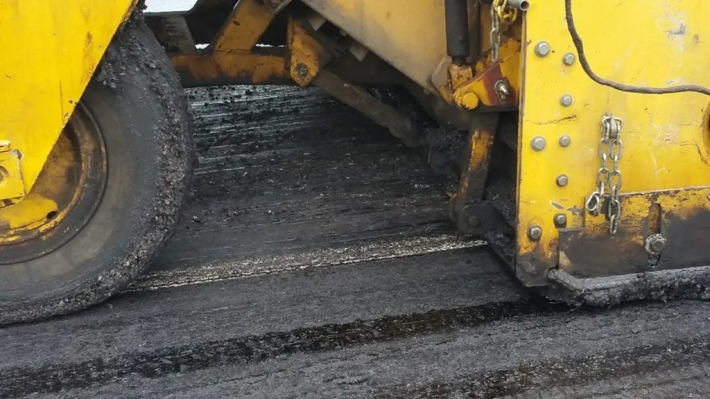
7.2.2.4 Augers
The mix carried to the back of the tractor unit by the slat conveyors is deposited in front of the augers (see Figure 82). Like the two slat conveyors, the augers on each side of the paver are operated independently of one another. The auger on one side of the paver is run in conjunction with the slat conveyor on that same side of the paver. In addition, the paver operator has the option of running the left or right conveyor and auger system in either manual or automatic mode. In automatic mode, a feed control sensor on that side of the machine controls the level of material at the outside edge of the auger. It is extremely important that the augers carry a consistent amount of mix across the front of the screed so that the head of material in front of the screed remains as constant as possible.
It is extremely important that the augers carry a consistent amount of mix across the front of the screed so that the head of material in front of the screed remains as constant as possible.
At the junction of the two augers in the center of the paver, adjacent to each side of the auger gearbox, there typically is a differently shaped auger (reverse auger) or a paddle used to tuck mix under the gearbox and ensure that the mix placement at this location is the same as that across the rest of the width of the mix being laid. A paver equipped with a pair of reverse paddles is shown in Figure 83 with the screed removed.
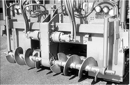
Source: Asphalt Institute
Figure 83. Paver Auger with Reversing Center Flights
If sufficient mix is not placed under the center of the screed and tucked under the gearbox, a longitudinal streak may be seen behind the paver at the center of the screed. This streak can be a form of segregation when gravity allows the mix from the two conveyors to flow under the gearbox. The surface texture of the mat at that location can be more open than that of the adjacent mix and is generally darker in color. This, however, is not always a segregation problem. Rather, the rougher texture and darker color can be caused by a lack of mix placed under the gearbox. When carefully measured, the elevation of the mix in the streak may be slightly below that of the surrounding mix—the streak is actually a low spot in the mat surface. If a gearbox streak is visible at the center of the main paver screed, installation of a reverse auger or paddle system on the paver must be verified. If the reverse augers or paddles are present, adjustments should be made to tuck more mix under the gearbox; worn augers or paddles should be replaced as necessary.
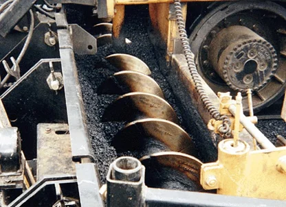
The area around the auger is often referred to as the auger chamber. The auger chamber, shown in Figure 84, is bounded by the front of the screed, the base upon which the mixture is being placed, and the rear of the tractor unit. Modern pavers are equipped with variable height augers that can be changed as needed.
Source: University of Idaho Visual Productions
Figure 84. Auger Chamber
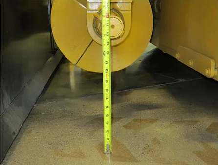
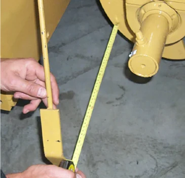
The horizontal distance from the auger to the screed front and the rear of the tractor unit should be equal if possible. A good rule of thumb is to maintain these distances at three times the maximum aggregate size of the mix.
The height of the auger from the base layer is normally set in accordance with the paving depth. A good rule of thumb is to set the distance from the base layer to the bottom of the augers equal to the loose lift thickness plus 2 to 2.5 times the maximum aggregate size in the mix being placed. When auger height is too low, imperfections in the mat texture can appear. The elevation of the bottom of the auger should never be even with or lower than the top of the mix being placed. If centerline segregation is noticeable, raise the augers an additional inch to allow more room for the mix to fill in the center of the auger box.
The amount of mix carried in the auger chamber should be as constant as possible. The proper depth of material on the augers is at the center of the auger shaft. The level of material carried in front of the screed should not be so low as to expose the lower portion of the auger flights. Further, the level of mix delivered to the screed should never be so high as to cover the upper portion of the auger. This constant level of material in front of the screed must continue all the way past the end of the auger. When paving wider than the basic screed, auger extensions and material confining plates (tunnel extensions) uniformly carry the mixture the full width of the screed. Ideally, the auger and tunnel extensions should be within 12–18 inches (0.3–0.5 m) from the end plate of the screed to minimize segregation and maintain a constant head of material in front of the screed, as shown in Figure 85.
Source: Reway
Figure 85. Uniform Head of Material at Axle Height
If the feed system is set and operating properly, the slat conveyors and augers on each side of the paver will rarely shut off; they will operate in a slow, continuous manner (20–40 revolutions per min). This continuous action of the conveyors and augers is accomplished by setting the proper position for the hopper flow gates (if any) and determining the correct speed setting for the conveyors and augers. The key to placement of a smooth pavement layer is the use of the material feed system to maintain a constant head (level) of material in front of the screed, primarily by keeping the slat conveyors and augers running as close to 100 percent of the time as possible. Intermittent operation of the slat conveyor and auger systems may cause roughness in the mat, as well as auger shadows and ripples in the mat behind the screed.
Material-control sensors precisely control the volume of material (head of material) in front of the screed. The auger/conveyor combinations on both the right and left sides of the paver work independently of each other, requiring separate material-control sensors. The sensors control the movement of material by starting, stopping, or running at variable speeds to furnish the correct volume of material to match the material demand based on the paving width, depth, and speed.
To operate properly, the sensors must monitor the live (constantly moving) head of material to provide a uniform flow of material in front of the screed. Original equipment manufacturers and aftermarket suppliers use different types of sensors and mount them in different positions to monitor and control the flow of material.
Two common types of material sensors are contact sensors and ultrasonic sensors. Contact sensors use a switching device, such as an on-off switch or potentiometer, that is activated by a paddle arm physically touching the flow of material. As the paddle arm, shown in Figure 86, approaches a near-vertical position, the auger drives start to deliver more mix until the arm reaches a preset angle and shuts off.
Source: University of Idaho Visual Productions
Figure 86. Paddle Switch
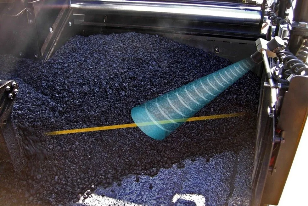
Ultrasonic sensors, shown in Figure 87, are non-contact devices that use sound waves to continuously monitor the face of material being carried in front of the screed. As mix is consumed, the distance being measured by the sensor increases and the auger systems are activated to replenish the volume of mix in front of the screed. To ensure an accurate reading, the sonic beam should be aimed perpendicular (approximately 90 degrees) to the active flow on the face of the mixture. The controller then varies the speed of the conveyors and augers on each side of the machine to maintain a constant level of mix across the front of the screed.
Source: Caterpillar, Inc.
Figure 87. Non-Contact Sensor
As the level of mix in front of the screed rises and falls, the speed of the feed system increases or decreases to maintain a constant level and uniform flow across the width of the screed. For the automatic feed control system to function properly, the feed sensors should be located as close to the outside ends of the augers as possible. If rigid paver screed extensions are used, the control arm should be mounted beyond the ends of the augers, just inside the end gate on the paver screed. If a hydraulically extendable screed is used, the location of the feed sensor control arm should be such that the amount of mix carried in front of the extensions is minimized. In most cases, this means the sensor should be mounted on the end gate of the paver screed and the sensor paddle or wand hung only a short distance in front of the end of the extendable screed.
7.2.3 Hopper Management
The amount of mix in the paver hopper should always be kept at a level above the top of the flow gates or tunnel openings at the back of the hopper. Doing so permits the paver operator to keep the conveyors on the paver full and thus maintain a constant head of material in front of the paver screed. This practice is particularly important between truckloads of mix to reduce segregation problems.
As shown in Figure 88, the sides, or wings, of the hopper are movable. It is considered a best practice to not fold (dump) the wings. However, some paver operators fold the wings of the paver between every load of mix. To prevent spillage of the mix out of the front of the hopper when the wings are folded, the operator often pulls down the amount of mix left in the hopper by continuing to run the slat conveyors, which results in the slat conveyor running empty. This can allow mix to segregate as it trickles down to the conveyor, as illustrated in Figure 89. The material in the outer edge of the wings can become segregated when discharged from the truck. In addition, the mix in the stagnant area of the hopper will begin to cool. This cooling can become significant, especially in cooler weather. This is a perfect formula for the truckload-to-truckload segregation discussed in Chapter 10.
Source: Asphalt Institute
Figure 88. Folding Hopper Wings
Source: Asphalt Institute
Figure 89. Poorly Managed Paver Hopper
To prevent asphalt mix from collecting in the corners of the paver hopper, a fillet can be placed in each corner of the hopper. A triangular piece of sheet steel bolted to the sides of the hopper will prevent mix from being carried in the corners of the hopper. It is also possible to simply not empty the wings of the paver during the paving day. The mix will cool and build up a natural angle of repose. At the end of the day, the cold material is removed from each wing area and transported back to the asphalt plant for recycling.
The best practice is to avoid asphalt mix from collecting or cooling in the wings by using a hopper insert as described in Chapter 6 and using an MTV or window elevator to feed the paver. The steep sides of a hopper insert provide for constant live action focused directly over the slat conveyors and eliminate segregation caused by the paver hopper. This also disconnects the transport vehicles from the paver, reducing dump time and inadvertent contact with the paver. Keeping the hopper full between truckloads of mix helps maintain a constant head of asphalt mix in front of the paver screed and reduces mixture and equipment heat loss. In addition, a paver hopper insert adds material storage, which helps maintain continuous paving.
When it is necessary to fold the wings, the wings should be emptied before the mix that collects in the corners of the hopper has cooled. The sides of the hopper should be slowly raised as soon as the haul truck has been emptied and has pulled away from the paver. A steady forward paving speed of the laydown machine should be maintained as the hopper sides continue to rise. The wings should be fully elevated before the amount of mix remaining in the hopper is lower than the top of the flow gates or the openings at the back of the hopper. The slat conveyors should never be visible at the time the wings are raised-or at any other time during the paving operation. The paver should be stopped before the tunnel openings or flow gates are visible, and the sides of the hopper then lowered.
When using a windrow elevator (shown in Figure 90 and Figure 91), the blades on the slat conveyor must be set at the right level to pick up as much of the mix that has been placed on the existing pavement as possible. Essentially, no mix should be left in the windrow, except a minimal amount in the low spots on the pavement surface when a leveling course is being placed. Any thin layer of material remaining will cool quickly and may result in difficulties in compacting the mix. In addition, longitudinal streaks may occur in the mat behind the paver at the same location as the outside edges of the windrow.
Source: Asphalt Institute
Figure 90. Windrow Elevator
Source: Asphalt Institute
Figure 91. Windrow Elevator Picking Up the Entire Windrow