10. Segregation
10.2 Recognizing Physical Segregation, Causes, and Solutions
The following are the most common types of segregation in the mat:
- Chevron-shaped spots at the beginning and end of truckloads.
- Center of paver streaks.
- Edge segregation.
- Continuous longitudinal streaks at either or both sides of the lane.
- Random spots that occur intermittently throughout the roadway.
Recognizing the type of segregation will make identifying its cause easier.
10.2.1 End-of-Truck Segregation
Truck-end (end of truckload) segregation shows up at regular intervals coinciding with the beginning and ending of each truckload discharge cycle. If the trucks are improperly loaded and unloaded, a segregation-prone mix will segregate when the mix starts being unloaded and then again when the last amount of mix comes out of the truck bed. It can be seen as a regularly spaced repetition of segregated areas down the road (see Figure 151).
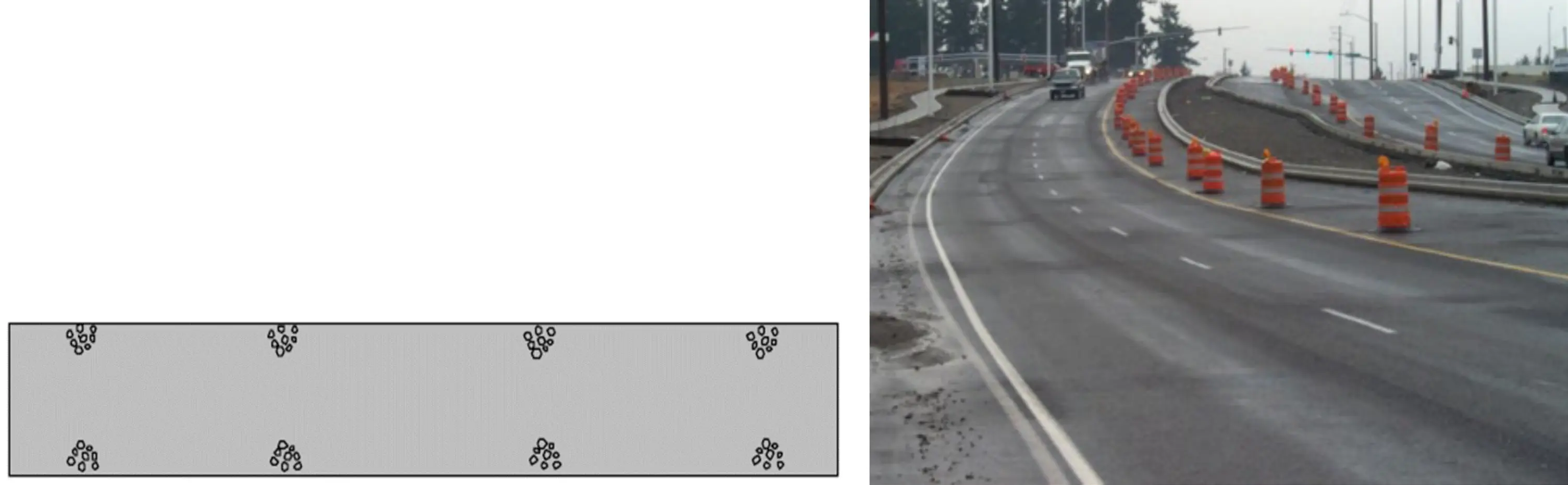
Source: Asphalt Institute
Figure 151. Examples of Truck-End Segregation
Truck-end segregation has many potential causes. The most common is improper loading of the haul truck from the silo. If the mix is placed in the truck bed in one drop from the silo, the coarse aggregate particles in the mix tend to run to both the front of the bed and the back tailgate. This rolling of the coarse aggregate is exacerbated if the plant operator continuously opens and closes the silo gates near the end of the truck loading procedure to ensure that the full allowable weight of mix is placed on the truck. Segregation occurring along the sides of the truck bed during loading translates to the paver when unloading into the paver hopper. Segregated material, or material trickling into the hopper at the outer box edge, will accumulate in the outer area of the hopper wings. All these segregation locations (front, side, and rear) exacerbate segregated mat areas behind the paver when the hopper wings are folded between every load.
10.2.2 Centerline Segregation
Centerline segregation (see Figure 152) is caused by the gear assembly that powers the augers. When placed too low, the augers and gear assembly may not provide enough clearance for the mix to counterflow to the center of the mat being placed. The result will be an insufficient, segregated mix in the center of the mat. When this occurs, the solution is to raise the auger gear assembly to give more clearance for the mix to flow to the center.
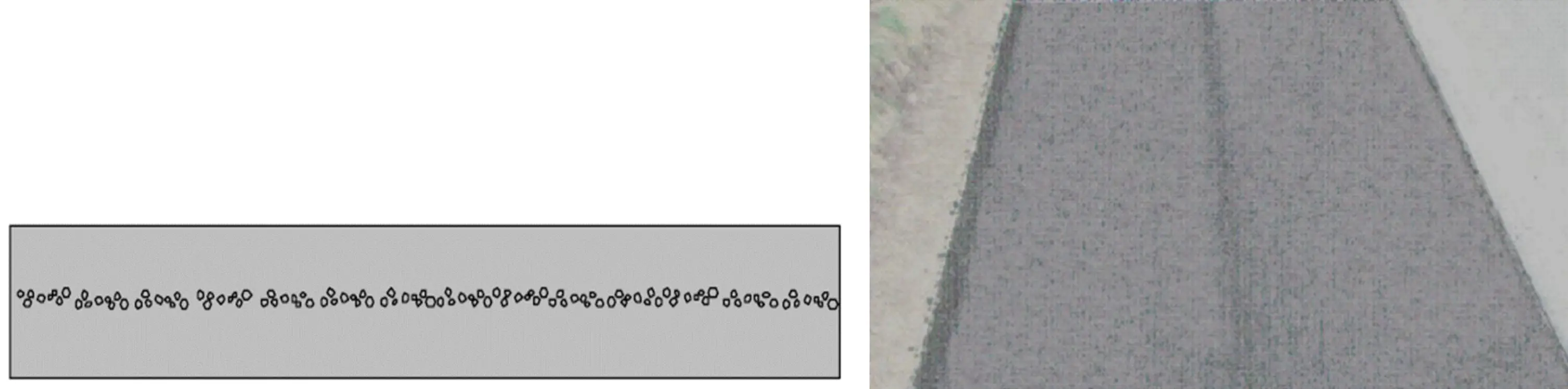
Source: Asphalt Institute
Figure 152. Examples of Centerline Segregation
Most paving machines have reverse flow or “kickback” augers right next to the auger drive assembly to alleviate centerline segregation. Sometimes these augers are worn or broken and need to be replaced.
10.2.3 Joint and Edge Segregation
When the mix is not confined properly at the outer ends of the screed, the mix can segregate. This is especially possible when paving wide without auger and tunnel extensions. The further the mix is pushed to the sides by the augers without an auger extension, the more segregation can be expected. In addition, it is recommended that the tunnel (confining plate) is extended to prevent the mix from segregating forward. When the mix flows forward, vertical segregation may occur, which is less visible on the surface. However, cores will show the larger aggregates at the bottom of the lift (see Figure 153).
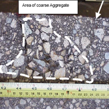
Source: American Society of Civil Engineers
Figure 153. Vertical Segregation (Top Different than Bottom of Cross Section)
Joint segregation can also occur when the rakers make corrections near the joint (see Figure 154). Recommendations are to overlap the joint approximately 1 inch and let the roller compact this overlap down without raking or luting the overlap. Any crushed aggregate will soon weather away.
Source: Asphalt Institute
Figure 154. Illustration of Joint Segregation
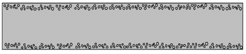
10.2.4 Whole- or Half-Width Mat Segregation
Whole- or half-width segregation (see Figure 155) can occur for several reasons.
The first reason is that one or both augers were provided insufficient mix. To avoid this, the mix should always be held close to the axle of the augers and at an even height across the auger chamber.
The second reason is that the mix was improperly loaded into the haul truck. If the mix is not loaded in the center of the width of the truck bed, the coarse aggregate particles in the mix may roll to one side of the truck bed and accumulate along that side. When the mix is delivered to the paver hopper, the segregated mix will be placed on the roadway along the same side, and the segregation will appear as a longitudinal streak on one side of the paver only.
Source: Texas Department of Transportation
Figure 155. Example of Half-Width Mat Segregation
A third reason is that the mix was improperly loaded into the silo. As the mix is deposited into the silo from the conveying device (slat conveyors, belt conveyor, or bucket elevator), the mix may be thrown to one side, causing the coarse aggregate particles to be separated from the finer materials (see Figure 156).
When the silo is emptied, the coarse aggregate is deposited on only one side of the truck. This segregated material then passes through the paver and is seen on one side of the mix after laydown. Further, if the truck is not loaded in the center of its width under the silo, rolling of the coarse aggregate particles may occur, and longitudinal segregation can appear on one side of the mat. The illustration in Figure 156 shows the mix being conveyed into a gob hopper, which should reduce segregation as it deposits the mix into the silo in batches.
These first four types of segregation (end-of-truck, centerline, joint and edge, and whole- or half-width mat) originate at the trucking and paving operations. People working onsite should be able to notice, recognize, and correct these types of segregation as soon as possible.
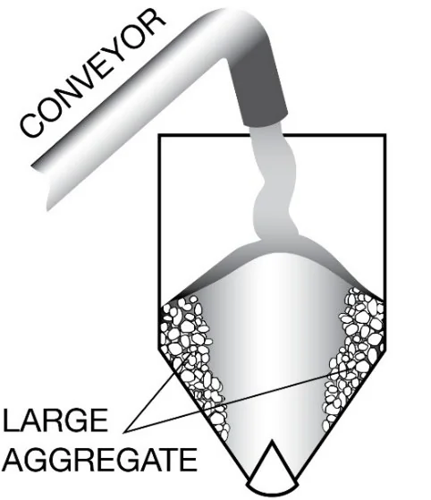
Source: National Asphalt Pavement Association
Figure 156. Segregation in the Silo at the Plant
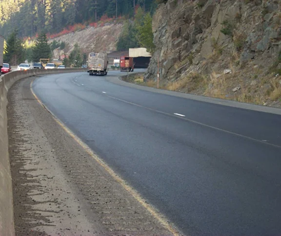
10.2.5 Random Segregation
Contrary to the previous four examples of segregation, random segregation typically originates at one or a combination of locations upstream from the trucking and paving operation. It is less easy to identify in the mat because of its randomness, in part due to remixing opportunities (see Figure 157). This is the type of segregation the paving crew has little to no possibility of correcting. Investigations as to the location and cause are more complicated and involve inspections starting at aggregate handling and then going through the mix production, storage, and discharge process. Its level of severity in the mat will dictate if and what remedy is required. Large aggregate, gap-graded, and SMA mixes are more prone to this type of segregation.
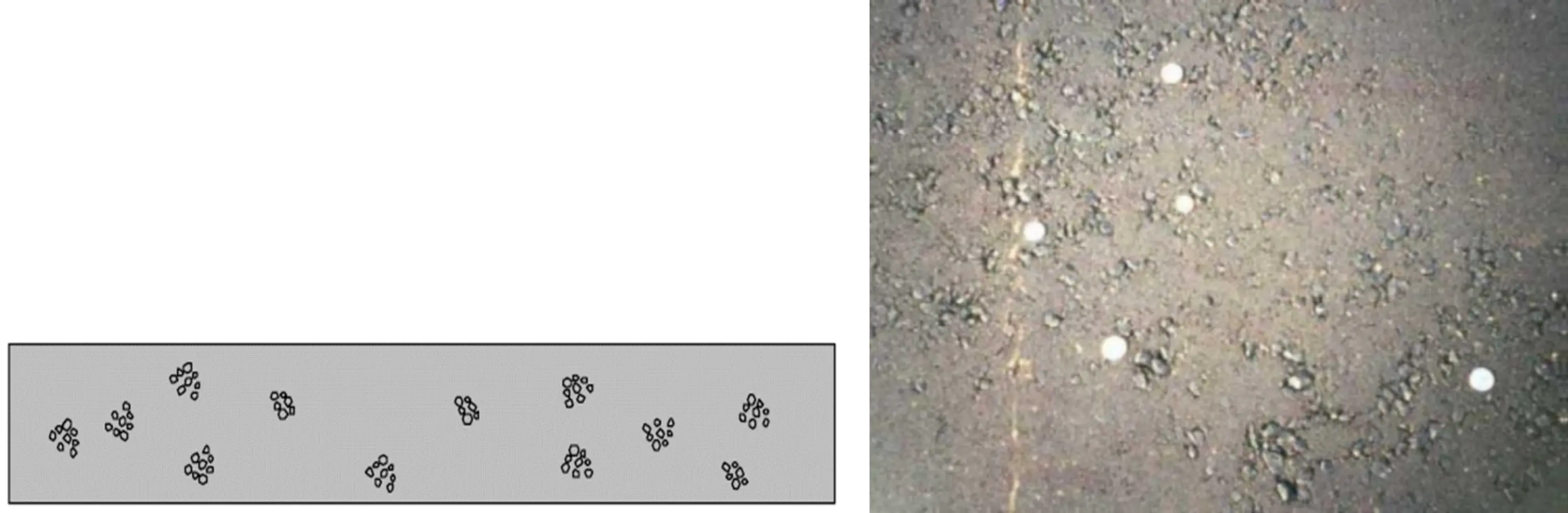
Source: Iowa Department of Transportation
Figure 157. Random Segregation
Segregated rock pockets are generally caused by improper handling of the aggregate in the stockpiles or cold-feed bins or improper storage of the HMA at the asphalt plant.
These problems are reduced when a batch plant is used to produce the mix without a silo, because the screens and hot bins in the plant recombine any segregated material before it is fed into the pugmill. Further, the pugmill blends all the aggregates together and normally eliminates any segregation that might have occurred previously. If a silo is used on a batch plant, however, the mix may segregate for all the same reasons that affect a mix produced in a drum-mix plant and passed through a surge or storage silo.