AAPTP
  • Small
  • Medium
  • Large
  • Small
  • Medium
  • Large
  • Home
  • Handbook
    • Asphalt Paving Handbook
    • Videos
    • Figures
    • Tables
  • Checklists
  • Abbreviations
  • About
  • HOME
  • Handbook
    • Asphalt Paving Handbook
    • Videos
    • Figures
    • Tables
  • CHECKLISTS
  • ABBREVIATIONS
  • About
1. Introduction
  • 1.1 Handbook Purpose and Organization
  • 1.2 Airfield Paving
  • 1.3 Asphalt Mixtures Defined and Classified
  • 1.4 Workmanship
  • 1.5 Certification and Accreditation Programs
2. Project Organization
  • 2.1 Introduction
  • 2.2 Project Documents
  • 2.3 Preconstruction Conference
  • 2.4 Ongoing Communication
  • 2.5 Ongoing Records
  • 2.6 Safety
3. Asphalt Materials and Mix Design
  • 3.1 Introduction
  • 3.2 Asphalt Binder: Grading Systems And Properties
  • 3.3 Aggregate Characteristics And Properties
  • 3.4 Mixture Volumetrics
  • 3.5 Asphalt Mix Properties
  • 3.6 Additives
  • 3.7 Mix Design Procedures
  • 3.8 Laboratory Versus Plan-produced Mixes
  • 3.9 Summary
4. Mix Production
  • 4.1 Introduction
  • 4.2 Material Storage and Handling
  • 4.3 Aggregate Cold Feed
  • 4.4 Aggregate Drying and Heating
  • 4.5 Batch Plants
  • 4.6 Drum and Continuous Plants
  • 4.7 Emission-Control System
  • 4.8 Temporary Mixture Storage
  • 4.9 Weighing and Loadout
  • 4.10 Safety
  • 4.11 Troubleshooting and Checklists
5. Surface Preparation
  • 5.1 Introduction
  • 5.2 Base Preparation for New Asphalt Pavements
  • 5.3 Asphalt Surface Preparation for Asphalt Overlays
  • 5.4 PCC Surface Preparation For Asphalt Overlays
  • 5.5 Tack Coat
  • 5.6 Summary
6. Mixture Delivery
  • 6.1 Introduction
  • 6.2 Planning
  • 6.3 Truck Types
  • 6.4 Proper Truck Loading
  • 6.5 Hauling Procedures
  • 6.6 Unloading the Mix
  • 6.7 Tracking Quantities
7. Mix Placement
  • 7.1 Introduction
  • 7.2 Tractor Unit
  • 7.3 Screed Unit
  • 7.4 Grade Control
  • 7.5 Layer Thickness
  • 7.6 Establishing Paver Speed
  • 7.7 Related Paving Operations
  • 7.8 Best Practices Checklists
8. Compaction
  • 8.1 Introduction
  • 8.2 Definitions
  • 8.3 Rollers
  • 8.4 Factors Affecting Compaction
  • 8.5 Compaction Variables Under The Operator’s Control
  • 8.6 Determination of Rolling Pattern
  • 8.7 Roller Checklists
9. Joint Construction
  • 9.1 Introduction
  • 9.2 Transverse/Construction Joints
  • 9.3 Longitudinal Joints
  • 9.4 Echelon Paving and Rolling
  • 9.5 Unconventional Longitudinal Joint Methods
10. Segregation
  • 10.1 Introduction
  • 10.2 Recognizing Physical Segregation, Causes, and Solutions
  • 10.3 Four Stages Where Segregation Can Originate
  • 10.4 Thermal Segregation
  • 10.5 Confirming and Quantifying Segregation
11. Quality Assurance
  • 11.1 Introduction
  • 11.2 Definitions
  • 11.3 General Types Of Specifications
  • 11.4 Quality Control Plan
  • 11.5 Sampling Methods
  • 11.6 Quality Control At The Plant
  • 11.7 Quality Control In The Field: Placement And Compaction
  • 11.8 Acceptance
12. Mat Problems
  • 12. Mat Problems
  • 12.1 Surface Waves
  • 12.2 Tearing (Streaks)
  • 12.3 Nonuniform Texture
  • 12.4 Screed Marks
  • 12.5 Screed Responsiveness
  • 12.6 Surface (Auger) Shadows
  • 12.7 Poor Precompaction
  • 12.8 Joint Problems
  • 12.9 Checking
  • 12.10 Shoving And Rutting
  • 12.11 Bleeding And Fat Spots
  • 12.12 Roller Marks
  • 12.13 Poor Mix Compaction
  • 12.14 Other Pavement Problems
Appendix
  • AAPTP Airport Asphalt Videos

10. Segregation

10.4 Thermal Segregation

Thermal segregation is not identifiable without infrared monitoring, and therefore it will often go unnoticed. As with physical segregation, there are many locations where thermal segregation may originate. This type of segregation occurs most often in trucking procedures and paver operation.

Thermal segregation is not identifiable without infrared monitoring, and therefore it will often go unnoticed.

In trucking, the mix cools more quickly near the edge, bottom, and top of the haul truck. This cooler material is not always remixed with the hotter material, leading to temperature segregation during laydown and compaction. The result can be more variability with in-place density and a nonuniform surface. This problem can only be detected by infrared technology. Truck beds are often insulated for longer haul distances to reduce the potential for temperature segregation.

The use of MTVs has shown benefit in reducing segregation. The MTV remixes the mix, reducing both physical and thermal segregation. Temperature segregation can be minimized with a balanced, uninterrupted paving operation.

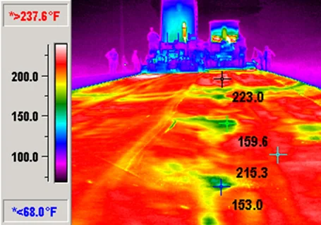
There are various ways to detect thermal segregation. These range from using a handheld infrared “gun” that spot checks surface temperature to more automated systems. These automated systems can scan the full width of the mat, record surface temperatures and location, and send the results in real time for analysis (see Figure 159). This allows for decisions regarding the construction operation and timely corrections if needed.

Figure 159. Paver Equipped with an Automated Infrared Scanner

Source: VÖGELE
Figure 159. Paver Equipped with an Automated Infrared Scanner

Research by Willoughby et al. (2001)1 concluded that if the mix temperature differential is less than 25 °F (~15 °C), generally consistent compaction can be expected. But if the mix temperature differential is 25 °F (~15 °C) or greater, differential compaction can occur, and the in-place air void content will fluctuate.

Highly segregated areas of coarse materials will tend to lose heat faster than surrounding areas of the freshly placed mat and appear in thermal imaging. Thermal segregation can be an indicator of the presence of physical segregation. Infrared data can identify cool spots in the mat and predict segregated areas (see Figure 160).

1K. Willoughby, J. Mahoney, L. Pierce, J. Uhlmeyer, K. Anderson, S. Read, . . . R. Moore, Construction-Related Asphalt Concrete Pavement Temperature Differentials and the Corresponding Density Differentials (Washington State Department of Transportation, 2001).

Figure 160. Segregated Areas (on right) Predicted by Cool Spots on Infrared

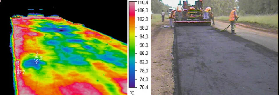
Source: Dorogi i Mosti Journal (top) and Pavement Interactive (bottom)
Figure 160. Segregated Areas (on right) Predicted by Cool Spots on Infrared

Previous Section
Next Section

© National Asphalt Pavement Association (NAPA). All rights reserved|Privacy Policy

6406 Ivy Lane, Suite 350 Greenbelt, Maryland 20770-1441

|888-468-6499
  • LinkedIn
  • Facebook
  • Twitter
  • YouTube
  • Instagram
Information

There are no items associated with the selected chapter.