AAPTP
  • Small
  • Medium
  • Large
  • Small
  • Medium
  • Large
  • Home
  • Handbook
    • Asphalt Paving Handbook
    • Videos
    • Figures
    • Tables
  • Checklists
  • Abbreviations
  • About
  • HOME
  • Handbook
    • Asphalt Paving Handbook
    • Videos
    • Figures
    • Tables
  • CHECKLISTS
  • ABBREVIATIONS
  • About
1. Introduction
  • 1.1 Handbook Purpose and Organization
  • 1.2 Airfield Paving
  • 1.3 Asphalt Mixtures Defined and Classified
  • 1.4 Workmanship
  • 1.5 Certification and Accreditation Programs
2. Project Organization
  • 2.1 Introduction
  • 2.2 Project Documents
  • 2.3 Preconstruction Conference
  • 2.4 Ongoing Communication
  • 2.5 Ongoing Records
  • 2.6 Safety
3. Asphalt Materials and Mix Design
  • 3.1 Introduction
  • 3.2 Asphalt Binder: Grading Systems And Properties
  • 3.3 Aggregate Characteristics And Properties
  • 3.4 Mixture Volumetrics
  • 3.5 Asphalt Mix Properties
  • 3.6 Additives
  • 3.7 Mix Design Procedures
  • 3.8 Laboratory Versus Plan-produced Mixes
  • 3.9 Summary
4. Mix Production
  • 4.1 Introduction
  • 4.2 Material Storage and Handling
  • 4.3 Aggregate Cold Feed
  • 4.4 Aggregate Drying and Heating
  • 4.5 Batch Plants
  • 4.6 Drum and Continuous Plants
  • 4.7 Emission-Control System
  • 4.8 Temporary Mixture Storage
  • 4.9 Weighing and Loadout
  • 4.10 Safety
  • 4.11 Troubleshooting and Checklists
5. Surface Preparation
  • 5.1 Introduction
  • 5.2 Base Preparation for New Asphalt Pavements
  • 5.3 Asphalt Surface Preparation for Asphalt Overlays
  • 5.4 PCC Surface Preparation For Asphalt Overlays
  • 5.5 Tack Coat
  • 5.6 Summary
6. Mixture Delivery
  • 6.1 Introduction
  • 6.2 Planning
  • 6.3 Truck Types
  • 6.4 Proper Truck Loading
  • 6.5 Hauling Procedures
  • 6.6 Unloading the Mix
  • 6.7 Tracking Quantities
7. Mix Placement
  • 7.1 Introduction
  • 7.2 Tractor Unit
  • 7.3 Screed Unit
  • 7.4 Grade Control
  • 7.5 Layer Thickness
  • 7.6 Establishing Paver Speed
  • 7.7 Related Paving Operations
  • 7.8 Best Practices Checklists
8. Compaction
  • 8.1 Introduction
  • 8.2 Definitions
  • 8.3 Rollers
  • 8.4 Factors Affecting Compaction
  • 8.5 Compaction Variables Under The Operator’s Control
  • 8.6 Determination of Rolling Pattern
  • 8.7 Roller Checklists
9. Joint Construction
  • 9.1 Introduction
  • 9.2 Transverse/Construction Joints
  • 9.3 Longitudinal Joints
  • 9.4 Echelon Paving and Rolling
  • 9.5 Unconventional Longitudinal Joint Methods
10. Segregation
  • 10.1 Introduction
  • 10.2 Recognizing Physical Segregation, Causes, and Solutions
  • 10.3 Four Stages Where Segregation Can Originate
  • 10.4 Thermal Segregation
  • 10.5 Confirming and Quantifying Segregation
11. Quality Assurance
  • 11.1 Introduction
  • 11.2 Definitions
  • 11.3 General Types Of Specifications
  • 11.4 Quality Control Plan
  • 11.5 Sampling Methods
  • 11.6 Quality Control At The Plant
  • 11.7 Quality Control In The Field: Placement And Compaction
  • 11.8 Acceptance
12. Mat Problems
  • 12. Mat Problems
  • 12.1 Surface Waves
  • 12.2 Tearing (Streaks)
  • 12.3 Nonuniform Texture
  • 12.4 Screed Marks
  • 12.5 Screed Responsiveness
  • 12.6 Surface (Auger) Shadows
  • 12.7 Poor Precompaction
  • 12.8 Joint Problems
  • 12.9 Checking
  • 12.10 Shoving And Rutting
  • 12.11 Bleeding And Fat Spots
  • 12.12 Roller Marks
  • 12.13 Poor Mix Compaction
  • 12.14 Other Pavement Problems
Appendix
  • AAPTP Airport Asphalt Videos

12. Mat Problems

12.8 Joint Problems

Youtube Video Icon

Watch Video

Transverse Joint Construction

Longitudinal Joint Construction

12.8.1 Description

Poor transverse joints are associated either with a bump at the joint, a dip in the pavement surface several feet (meters) beyond the joint, or both. Poor LJs (see Figure 166) between passes of the paver are usually characterized by a difference in elevation between the two lanes, by raveling of the asphalt mix at the joint, or both. The area adjacent to the LJ is usually depressed below the level of the surrounding pavement surface.

Figure 166. Poor Longitudinal Joint Due to Unsatisfactory Construction

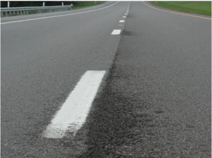
Source: Asphalt Institute
Figure 166. Poor Longitudinal Joint Due to Unsatisfactory Construction

12.8.2 Causes

Joint problems are caused by poor construction of the joint, inadequate compaction of mix placed along the joint, improper startup procedures when paving resumes after a stoppage, or improper construction and removal of tapers.

12.8.3 Solutions

One key to a good transverse joint is to construct the joint at the end of the paving day at a location in the mat where the layer thickness is constant (see Section 9.2 for a discussion of joint construction). This means the compacted thickness of the mat at the end of the paver run is the same as that of the previously placed mat. For airfields, a good point is at the end of the pavement, since this will eliminate a transverse joint.

At the start of paving the following day, the paver screed should be placed on blocks on the cold side of the transverse joint. The thickness of the blocks should be related to the depth of the course being laid—approximately 1/4 inch (5 mm) thick for each 1 inch (25 mm) of compacted layer thickness. The front edge of the paver screed should then be placed directly over the vertical face of the joint. Once the paver pulls away from the joint, the right amount of mix should be in the right place, and only minimal raking, if any, normally needs to be done. The mix at the joint should then be compacted as quickly as possible.

For LJ construction (see Section 9.3), it is extremely important to compact the edge of the first lane properly. Doing so requires that the vibratory or static steel-wheel roller hang out over the unsupported edge of the mat by about 6 inches. This practice provides the most compactive effort along the unconfined edge without causing undue lateral displacement of the mix along the edge of the pavement.

For LJ construction, it is extremely important to compact the edge of the first lane properly. Doing so requires that the vibratory or static steel-wheel roller hang out over the unsupported edge of the mat by about 6 inches.

When placing the second (adjacent) pavement lane, the end plate on the paver screed should overlap the first lane by 1 to 1-1/2 inches. Minimal raking, if any, should be done on the mix placed over the first lane. The rollers—vibratory, pneumatic tire, and static steel-wheel—should operate on the hot side of the joint and extend over the joint on the cold side by approximately 6 inches. The same number of roller passes should be made over the LJ as over each point in the interior of the HMA mat.

12.8.4 Effects on Performance

A poor transverse joint will not affect pavement performance to any significant degree if proper density levels are obtained by the compaction equipment. A poor ride will usually be the only negative result. An improperly constructed LJ, however, can seriously decrease the serviceability of the pavement structure. A poorly placed and compacted joint will ravel and cause one side of the joint to be lower than the other. FOD from the raveling of the pavement is a huge concern on all airfields. If the density level is too low, the whole pavement layer thickness at the LJ may wear away under the action of traffic. A poor joint will also be porous, allowing water to enter the underlying pavement courses.

Previous Section
Next Section

© National Asphalt Pavement Association (NAPA). All rights reserved|Privacy Policy

6406 Ivy Lane, Suite 350 Greenbelt, Maryland 20770-1441

|888-468-6499
  • LinkedIn
  • Facebook
  • Twitter
  • YouTube
  • Instagram
Information

There are no items associated with the selected chapter.