4. Mix Production
4.3 Aggregate Cold Feed
The cold-feed systems on asphalt batch and drum-mix plants are similar. Each consists of cold-feed bins, feeder conveyors, a gathering conveyor, and a charging conveyor. The aggregate cold-feed system receives the aggregate material from the stockpiles, proportions the aggregate to achieve the gradation specified, and delivers the aggregate to the dryer. On most plants, a scalping screen is included in the system at some point.
If RAP is being fed into a plant, separate cold-feed bin(s), feeder belt and/or gathering conveyor, scalping screen, and charging conveyor are necessary to handle the extra material.
4.3.1 Cold-Feed Bins
The flow of aggregate through a plant begins at the cold-feed bins (see Figure 24). The plant is equipped with multiple bins to handle the different sizes of aggregate used in the mix. A bulkhead or divider should be used between each cold-feed bin to prevent overflow of the aggregate from one bin into another. If bins overflow, the commingled aggregate sizes can significantly alter the gradation of the mix and performance of the mixture produced.
Uniform flow of properly sized aggregates is crucial to achieve consistent production. Once an aggregate material is introduced into the cold-feed bins, the plant cannot detect or correct inconsistencies in gradation or aggregate quality.

Source: Asphalt Institute
Figure 24. Loading Aggregate Cold-Feed Bins
4.3.2 Bin Feeders
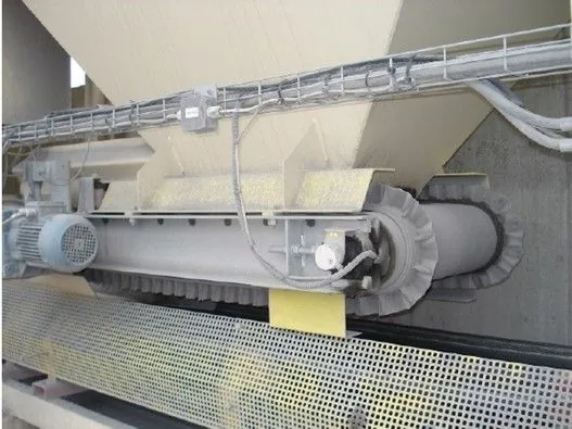
Aggregates are delivered through calibrated feeder gates to belt feeders (short, variable-speed conveyor belts) located directly under each cold-feed bin (see Figure 25 and Figure 26). The rate of material from each bin is controlled by the feeder belt speed and feeder gate opening. This system provides a very consistent control of the aggregate flow from the individual bins onto the main conveyor that leads to the dryer.
Source: Asphalt Institute
Figure 25. Cold-Feed Bin Feeder Belt
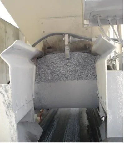
Each cold-feed bin opening is typically equipped with a flow sensor (see Figure 26) placed directly in the material stream. If a bin runs empty or the discharge opening becomes clogged, a “no-flow condition” alert is sent to the plant computer.
Source: Asphalt Institute
Figure 26. Bin Feed Aggregate Sensor
Because a uniform flow of properly sized aggregates is so important to consistent production, a check should be made before and during production to be certain that the feeder system is functioning properly. The following conditions are important for maintaining uniform flow and consistency:
- Correct sizes of aggregates in stockpiles and cold bins.
- No segregation of aggregate stockpiles.
- Accurately calibrated and secured feeder gates.
- No obstructions in feeder gates or in cold bins.
- No material clumping causing “bridging” that interrupts uniform flow.
- Correctly functioning bin vibrators, if equipped, to prevent bridging.
- Correct speed control settings.
4.3.3 Mineral Filler/Hydrated Lime Additive System
Extremely fine materials, generally referred to as the “dust” (minus 0.075-mm sieve) fraction of the aggregate gradation, are a critical component of any durable asphalt mix.
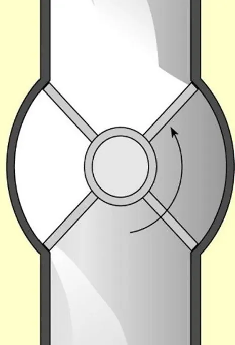
Mineral filler, such as hydrated lime, Portland cement, fly ash, limestone dust, or baghouse fines, should be stored in a silo or other appropriate container and delivered to the plant through a vane feeder system (see Figure 27) or small weigh hopper. The speed of the feeder is calibrated to the aggregate being delivered to the drum. The silo is normally equipped with an aerating system to keep mineral filler from packing into a tight mass and bridging the feeder opening. If the flow of filler is restricted, the vane feeder will still rotate, but no material will be sent to the plant.
Source: Asphalt Institute
Figure 27. Vane Feeder Schematic
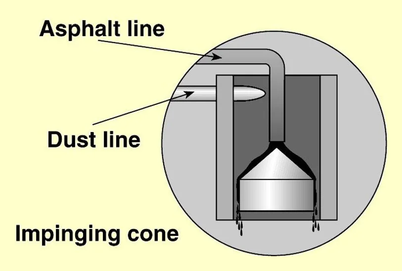
Once metered, a pneumatic system or auger is used to move the material to the required location. In a drum mixer, it is typically located near the binder supply line in the drum. This proximity allows the liquid binder to capture the extremely fine material, preventing it from being diverted back to the dust collection system. Terminating both supply lines under a hood or impinging shroud (see Figure 28) will add extra protection by separating the fine material from the high-velocity airstream flowing through the dryer.
Source: Asphalt Institute
Figure 28. Drum Mixer Impinging Hood or Cone
To continuously meter the dust, storage silos typically make use of a weigh hopper or pod to accurately meter the rate of material flowing from storage into the mixing process. If this method is not available, frequent checks on the calibration of the feeding and weighing mechanisms should be performed.
Some agencies require the use of hydrated lime as an anti-stripping agent. There are many methods in use that successfully incorporate hydrated lime into a mix. A common method is to add hydrated lime directly to moist aggregate or combine it with water to make a slurry and then mix it with the aggregate in a separate pugmill. Generally, the lime-aggregate mixture is fed directly into the plant after mixing. However, an aggregate treated with a lime slurry mixture may be stockpiled to allow for additional marinating and drying before introduction into the plant for mixing. For more information on the use of hydrated lime as an anti-stripping agent, refer to Section 3.6.3.
4.3.4 Reclaimed Asphalt Pavement
The cold-feed system for handling RAP is essentially the same as the conventional cold-feed system for new aggregate. On most plants, as shown previously in Figure 21 and Figure 22, a separate cold-feed bin is used. The bin (or bins) is like the cold-feed bins used for aggregate except that all four sides of the RAP feed bins are usually much steeper. The steeper sides reduce the tendency of the reclaimed material to bridge the opening at the bottom of the bin. The RAP should be passed through a scalping screen to remove any oversized pieces of asphalt mixture or deleterious material.
It is an important point to keep in mind that RAP sources must be properly and randomly tested for consistency prior to producing the mixture. If RAP consistency is variable, using a higher percentage will increase the probability that the final product will be out of specification. This is one reason why some specifying agencies frequently ask for RAP sources to be stockpiled separately and why RAP percentages are often limited in the final product.
RAP sources must be properly and randomly tested for consistency prior to producing the mixture.
One way to reduce RAP variability is to fractionate it into two sizes—a fine material and a coarse material. The splitting screen size may range from 9.5 to 19 mm (3/8 to 5/8 of an inch). The material is then proportioned into the mix as if it were two sources of material. Additional information concerning recycled material is available in Section 3.3.9.