4. Mix Production
4.4 Aggregate Drying and Heating
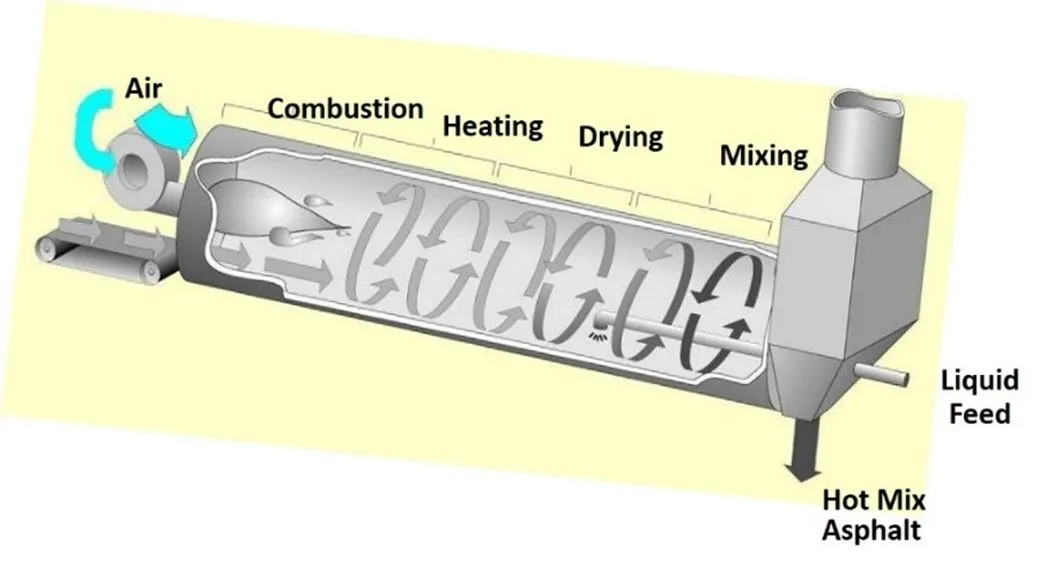
From the cold-feed bins, aggregates are delivered to the dryer drum. The dryer accomplishes two things: it dries the aggregate and heats the aggregate to the required temperature.
4.4.1 Aggregate Dryer
The dryer is a sloped, rotating cylinder ranging from about 5 to 10 ft (1.5 to 3 m) in diameter and 20 to 40 ft (6 to 12 m) in length (see Figure 29). It has an oil or gas burner with a blower fan to provide the primary air for combustion of the fuel. The exhaust fan is a critical element that pulls the heated gases through the dryer and assists in the complete combustion of burner fuel. The exhaust fan is located beyond the dryer, at the end of the dust control equipment (discussed further in Section 4.7).
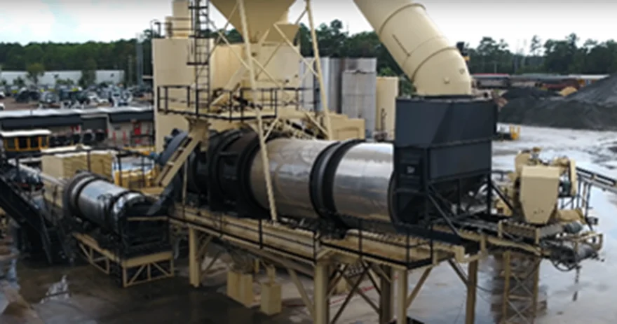
Source: National Asphalt Pavement Association
Figure 29. Typical Batch Plant Dryer
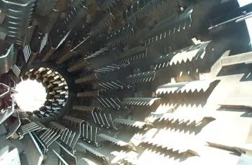
The inside shell of the drum has bolted-on or welded-on longitudinal troughs and channels, called flights, which lift the aggregate and drop it in a continuous shower or “veil” through the heated gases flowing through the dryer (see Figure 30). The slope of the dryer; its rotation speed, diameter, and length; and the arrangement and number of flights all combine to determine the time the aggregate will spend in the dryer.
Source: Asphalt Institute
Figure 30. Uniform Veil of Aggregate in Dryer
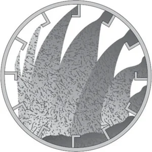
Near the open flame area of the burner, also known as the combustion zone, special flighting traps the aggregate near the wall of the dryer and carries it over the top of the flame. This prevents individual particles from passing through the flame and interfering with complete fuel combustion. Maintenance of the flights in the drum to produce a uniform veil of aggregates (see Figure 31) across the drum is necessary to efficiently produce a consistent mix.
Source: Stansteel/Hotmix Parts & Supply
Figure 31. Different Types of Dryer Flights
4.4.1.1 Aggregate Dryer Types
There are two basic types of dryers: parallel-flow and counterflow. They are named for the relationship between the flow of the aggregate and the flow of the hot gases within the dryer. Regardless of the dryer style, the principles of drying aggregate are the same.
In parallel-flow dryers (see Figure 32), the aggregate and the air flow in the same direction. Cold aggregate is introduced into the dryer at the same end as the burner (the higher end of the drum), and the materials flow toward the lower end of the dryer parallel to the airflow.
Source: IIT Kharagpur
Figure 32. Parallel-Flow Dryer
In counterflow dryers (see Figure 33), the aggregate and air flow in opposite directions, counter to each other. The burner is in the lower end of the drum and the aggregate is carried down through the drum against the airflow. Counterflow dryers are more common because they provide more efficient heat transfer than parallel-flow dryers.
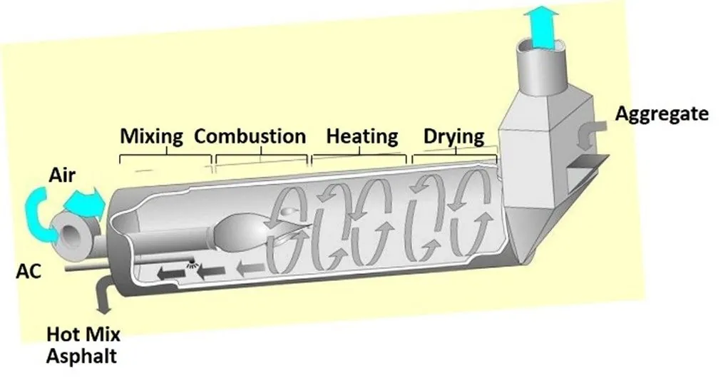
Figure 33. Counterflow Dryer
4.4.1.2 Aggregate Dryer Capacity
The drying process controls the overall production rate of the entire facility. Asphalt mix cannot be produced faster than the aggregate can be dried and heated. Dryer capacities are rated for heating and drying aggregate at a specific moisture content (typically 5 percent). If the aggregate moisture content is higher, the quantity of aggregate being fed to the dryer must be reduced to dry the aggregate properly. Consequently, there is a drop in the dryer’s production. Dryer slope, flighting, product temperature, aggregate type, atmospheric conditions, and elevation will also impact dryer performance.
If the aggregate moisture content is higher, the quantity of aggregate being fed to the dryer must be reduced to dry the aggregate properly.
Aggregate moisture content should be determined at least twice a day and more often if moisture conditions change, such as after rainfall. The average moisture content of the aggregate coming into the plant dryer or drum mixer is needed by the plant control system to permit proper setting of the burner controls, calculation of the dry weight of the incoming aggregate, and determination of the binder supply for drum-mix plants.