4. Mix Production
4.5 Batch Plants
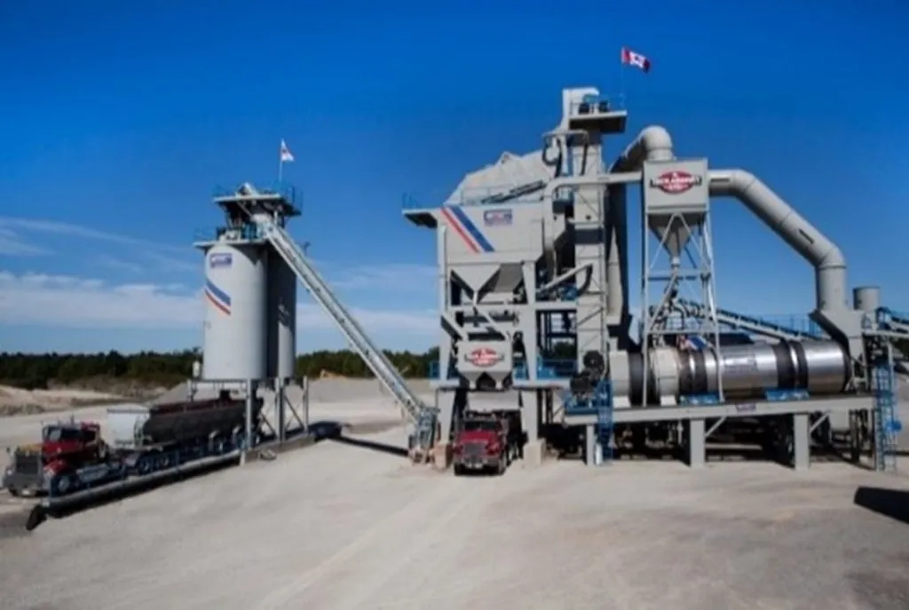
Batch plants (shown in Figure 34) get their name from the fact that during operation they produce asphalt mixture in batches, one batch at a time, one after the other. The size of a batch varies according to the capacity of the plant’s pugmill (the mixing chamber where aggregate and asphalt binder are blended). Batch sizes can vary from 2,000 to 10,000 lbs (900 to 4,500 kg).
Source: Gencor Industries
Figure 34. Asphalt Batch Plant
4.5.1 Operations
As discussed earlier, the basic operations of both batch and drum-mix plants are similar except for the aggregate and asphalt mixing procedures. Material storage and handling, aggregate cold feeds, and aggregate heating and drying, as well as emissions control, are all quite similar for batch and drum-mix plants. This section will focus on the mixing operations that are unique to a batch plant.
4.5.2 Screening and Storage of Hot Aggregate
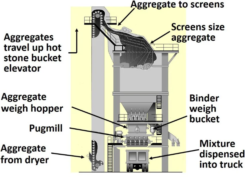
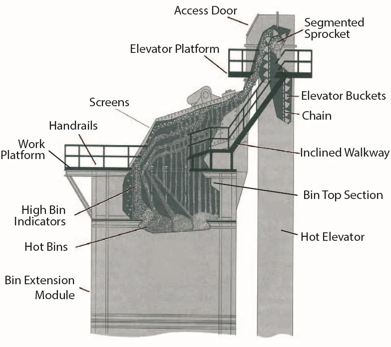
After the aggregate has been heated and dried, it exits the dryer into a hot elevator. The hot elevator is a nearly vertical, enclosed bucket conveyor that carries the aggregate to the top of the “batching tower” (see Figure 35). The aggregate is discharged from the elevator into a screening unit. The hot aggregate passes over a screening unit that separates it into various-size fractions and deposits those fractions in hot bins.
Source: Asphalt Institute
Figure 35. Batching Tower
The screening unit includes a set of several different-size vibrating screens inside a large housing. The screens separate the aggregate into specific sizes. The first screen is a scalping screen that removes oversized aggregate. This is followed by two to four screens,decreasing in size from top to bottom. The sizes of the screens used will depend on the plant and the gradation of the aggregate for the mix being produced (see Figure 36). The screens are designed to allow the finest particles to drop completely through to the first hot bin, and larger particles move along the screens to be deposited into the subsequent bins.
Source: Asphalt Institute
Figure 36. Screening Decks and Hot Bins
4.5.3 Hot Bins
Hot bins are located directly below the screening unit and used to store the heated and screened aggregates. Hot bins have indicators that tell when the aggregates fall below a certain level. These indicators may be either electronic or mechanical. Each bin should also be equipped with an overflow pipe or a high bin indicator to prevent excessive amounts of aggregate from spilling into the other bins. When a bin severely overfills, the screen above it rides on the overloaded aggregate, resulting in a heavy carryover and possible damage to the screen.
Hot bins are referred to by their total capacity. This can be as low as 20 tons for a small, portable batch plant to as large as 300 tons for a large, stationary plant. A very common capacity is in the range of 40 to 80 tons (36 to 72 tonnes).
Not all aggregate passes through the screening deck and hot bins. Mineral filler and dust returning from the baghouse are fed directly into the weigh hopper and weighed as a separate component.
4.5.4 Hot-Bin Sampling
Batch plants are equipped with devices for sampling hot aggregate from the bins. Most plants utilize a sample container mounted at the end of a control rod. When placed under the hot-bin feeder or gate, the containers catch a complete cross-section of the aggregate flow as it drops out of the bin. Some plants have a device to divert the flow of aggregate from the hot bin to a sample container. It is essential that such containers be properly located when taking the sample so that they collect a representative sample of the material.
During production, as the aggregate flows over the plant screens, the finest particles fall first into one side of each bin, and coarser particles travel along the screen to the other side of each bin. When material is drawn from the bin, the aggregate stream consists predominantly of finer material on one side and coarser material on the other. Therefore, the position of the sampling device in the stream of material discharged from a bin determines whether the sample will be composed of a finer portion, a coarser portion, or an accurate representation of the material in the bin. This condition is especially critical in the first or Number 1 (finest aggregate) bin since the material in this bin strongly influences the amount of asphalt binder required in the mix.
4.5.5 Calibration
Normally it is the contractor’s responsibility to calibrate the asphalt plant; however, agency inspectors are often required to observe and be aware of the procedures used to arrive at an aggregate combination that meets the JMF.
It is important to understand that the hot-bin percentages used to calculate batch weights are different than the cold-feed bin percentages. For the plant to produce the desired JMF specified in the mix design, the content of each hot bin must be analyzed. Once the plant is started and allowed to reach proper operating condition, a sample of aggregate is taken from each hot bin and analyzed. Once the gradation of material in each hot bin is determined, the exact percentage by weight from each hot bin to meet the design mix can be determined.
The hot-bin percentages used to calculate batch weights are different than the cold-feed bin percentages
It is possible for a batch plant to change mixture types from truckload to truckload. However, if the aggregate being supplied by the cold feed is not balanced with the aggregate discharge from the hot bins, the system can become unbalanced and result in one bin overflowing and another being starved of material. The smaller the hot bin size, the more easily it becomes unbalanced. The plant operator can only change the amount of hot-bin material being discharged into the mixer. This can be altered for a load or two (depending on the size of the hot bins), but when the plant becomes severely unbalanced, production will need to cease, and the plant cleared of excess aggregate in the bins to reestablish a balanced condition. Continual use of overflow chutes from the hot bins indicates the mixture being produced is not in sync with the gradation of the material being proportioned by the cold-feed system.
4.5.6 Drawing Material from the Hot Bins
The aggregate is drawn from each hot bin, one bin at a time, into a weigh hopper positioned above the actual mixing chamber or pugmill. The weigh hopper is continuously weighed, and the contribution of each hot bin is accurately determined for each batch of mix produced.
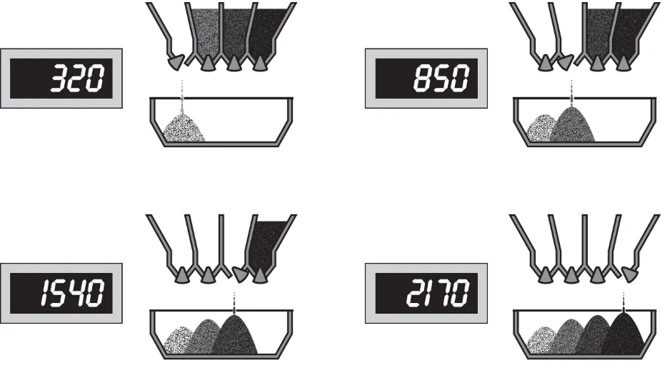
Usually, the coarsest aggregate is drawn (or pulled) first, the intermediate size aggregates next, and the finest aggregate last. This system allows the most efficient utilization of the available volume in the weigh hopper since the finer aggregates will partially penetrate the voids in the coarser aggregates. This information is normally entered into a computer that controls the opening and closing of the bins to obtain the correct amount of aggregate from each hot bin. Figure 37 illustrates how the cumulative scale settings are used to control the weight of aggregate drawn from each bin.
Source: Asphalt Institute
Figure 37. Cumulative Hot-Bin Batching
4.5.7 Introducing the Asphalt Binder
From the weigh hopper, the aggregate is deposited into the plant’s pugmill (mixing chamber), where it is blended with the proper proportion of asphalt binder. In a typical plant system, the binder is weighed separately in weigh buckets—which are enclosed, heated, and sealed units—before being introduced into the pugmill. When the weight of asphalt binder in the bucket reaches a predetermined level, a valve in the delivery line closes to prevent the excess binder from being discharged into the bucket. The binder is then pumped through spray bars into the pugmill (see Figure 38).
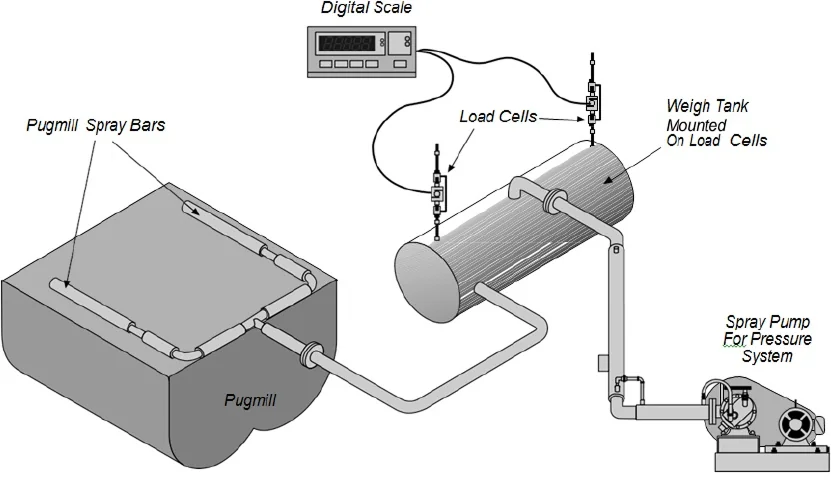
Asphalt cement is weighted separately in a load cell-mounted weigh tank.
Source: Asphalt Institute
Figure 38. Batch Plant Binder Supply System
4.5.8 Pugmill Mixing
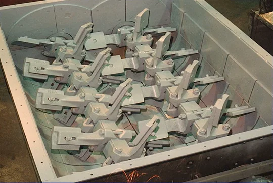
Once the batching of aggregate and asphalt binder is completed, the aggregate is transferred to a mixing chamber, called a pugmill (shown in Figure 39), which is located immediately below the weigh hopper.
Typical batch plants use a twin-shaft pugmill, which consists of a mixing chamber with two horizontal shafts, on which several cross arms are mounted. Pugmills are lined with sacrificial steel wear plates to absorb the scouring effect of mixing hard, angular aggregate particles.
Source: Asphalt Institute
Figure 39. Batch Plant Pugmill
At the end of each cross arm is a metal plate, commonly called a mixing paddle. These paddles must be adjusted to avoid dead zones in the pugmill. Dead zones are areas where the materials are not properly agitated. To avoid this situation, the paddles should be adjusted so that the clearance between the paddle tips and the mixer liner is less than one-half the maximum size aggregate used in the mix. Worn or broken paddles should be replaced as soon as possible.
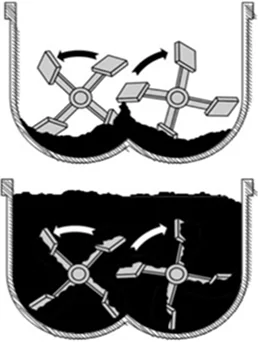
If the pugmill is overfilled or underfilled, nonuniform mixing will occur (see Figure 40). With too little material in the pugmill, the paddles are not able to adequately mix the material. If the pugmill is overloaded, part of the material will tend to float on the top of the batch and not be thoroughly mixed. These situations can be avoided by following the manufacturer’s rated batch size. Normally the manufacturer’s rating is based on a percentage of the pugmill live zone. This live zone is the net volume of the inside of the pugmill below a line extending across the top arc of the mixing paddles. The volume of the shafts, cross arms, paddles, and liner is not included in this volume. In most cases, the maximum operating efficiency of a pugmill is achieved when the paddle tips are barely visible at the surface of the material during mixing.
If the pugmill is overfilled or underfilled, nonuniform mixing will occur.
Source: Asphalt Institute
Figure 40. Incorrect Pugmill Operation
The complete mixing cycle is the blending of asphalt binder, aggregates, and mineral filler to produce mix. The length of time between the opening of the weigh-box gate and the opening of the pugmill discharge gate is referred to as the batch mixing time. The batch time typically consists of two stages: a dry mixing stage and a wet mixing stage. The dry mixing stage is a short portion of the batch time used (10 seconds or less) to mix the aggregates before introducing the binder. The wet mixing stage is the mixing time after the binder has been introduced into the mix. The total batch mixing time must be long enough to produce a homogenous mixture of evenly distributed and uniformly coated aggregate particles. To monitor batch mixing time, most job specifications require the use of some type of timing device.
The total batch mixing time must be long enough to produce a homogenous mixture of evenly distributed and uniformly coated aggregate particles.
Mixing time may be set within specification limits for each mix in any given plant by the procedure described in AASHTO T 195 or ASTM D2489, Determining Degree of Particle Coating of Bituminous-Aggregate Mixtures. This system bases the degree of mixing on the percentage of coarse particles that are 100 percent coated with asphalt binder and correlates it with mixing time. Only coarse particles are used in this procedure because they are the last to be coated in the mixing process.
4.5.9 Batch Plant Automation
A batch plant control room (shown in Figure 41) typically has the following plant control areas:
- A master motor control console with start/stop switches for all plant motors, which are interlocked for safety and plant protection.
- A computer system that controls the motor starts and stops in a pre-planned and programmed sequence so they cannot be started unless previous conditions are met, i.e., the main conveyor belt cannot be started unless the dryer drum is turning, or the burner cannot fire up unless the exhaust fan is running.
- A burner control console with start/stop switches, increase/decrease switches, and the safety circuits required for the burner.
- A cold-feed control console with start/stop switches and increase/decrease switches to control the feed from individual cold bins to the dryer. Many cold-feed control consoles have manual/automatic selector switches that allow the operator to control the feed from each bin manually or to recall a cold-feed mix formula from memory, select the desired production rate, and automatically feed the dryer to match the batch cycle requirements. A separate computer is sometimes found dedicated to this type of cold feed automation.
- A computerized batch automation that resides in a batch control console.
- A draft control and air emission-control console that houses controls for the exhaust fan, dryer draft, and air emission-control equipment.
- Mineral filler, baghouse fines return, hydrated lime control, or other additive control panels, if that equipment is required for the project.

Source: National Asphalt Pavement Association
Figure 41. Batch Plant Control Room
4.5.10 Recycling with a Batch Plant
All recycling methods in batch plants utilize conductive heat transfer instead of convective heat transfer. Conductive heat transfer is accomplished by mixing cold recycled material with hot aggregate. Convective heat transfer is accomplished by exposing cold aggregate to hot gases. In batch plants, regardless of the recycling method used, superheated hot virgin aggregate is used to heat the cold, moist RAP. A brief discussion of common batch plant recycling and heat transfer methods is described below.
4.5.10.1 Weigh-Box Recycling Technique
With the weigh-box method of recycling, cold (unheated), moist RAP is added to the weigh hopper, where the batch controller weighs it as an additional aggregate material. The feed bin for the RAP and the elevated conveyor that is required to reach the weigh hopper typically have large motors and pneumatic clutches with brakes so they can be started and stopped instantly. This facilitates feeding just the right amount of RAP into the weigh box.
The RAP is then mixed with the superheated virgin aggregates in the weigh hopper. Conductive heat transfer occurs in the weigh hopper and the pugmill throughout the dry mixing stage. During the heat transfer process, the moisture in the RAP generates a significant amount of steam. The pugmill and weigh hopper area must be enclosed and vented to the emission-control system to control this instantaneously large volume of steam and dust.
While recycled mixes with up to 50 percent RAP content can theoretically be produced with this method, in day-to-day practical field conditions, it is rare to see RAP percentages higher than 25 percent with the weigh-box heat transfer method. This is because RAP moisture contents typically run in the 3- to 5-percent range, and elevating the aggregate temperature beyond 600 °F (315 °C) is difficult due to dryer limitations. Also, dryer exit gas temperatures can impose a practical limit if baghouses are used in the plant. The filter fabric used in the bags of the baghouse has temperature limitations, and a massive increase in fuel consumption is required to obtain the required aggregate temperature.
4.5.10.2 Pugmill Recycling Technique with Separate RAP Weigh Hopper
This method of recycling uses a separate weigh hopper for RAP, which empties its batch component into the pugmill. Typically, a high-speed slinger conveyor is used to convey RAP from the RAP weigh hopper to the pugmill, although a chute or high-speed screw conveyor can also be used. The same heat transfer, steam release, and practical limits apply to this approach as apply to the weigh-box method of batch plant recycling. By adding an additional weigh hopper to the batch facility, the RAP is conveyed into and weighed in its own hopper while the virgin asphalt binder and virgin aggregates are being weighed separately, which slightly reduces the batching time.
4.5.10.3 Bucket Elevator Recycling Technique
This approach to batch plant recycling eliminates the steam release typical of the mixer and pugmill heat transfer methods. In the bucket elevator recycling method, cold, moist RAP is mixed with the superheated virgin aggregate as the aggregate exits the dryer and enters the bucket elevator.
The continuous steam release resulting from conductive heat transfer occurs in the buckets as the virgin aggregate/RAP mixture makes its way to the screen deck. The steam released from the RAP is carried away by the fugitive dust ductwork already fitted to the bucket elevator and screen deck.
Because the RAP is being continually blended with the virgin aggregate, belt scales are used on both the conveyor feeding virgin aggregate into the dryer and the conveyor feeding RAP into the bucket elevator. The scales ensure the maintenance of a proper ratio of RAP to virgin aggregate.
Gradation control for mix production is accomplished in one of two ways, and both are different from that in a batching facility producing completely virgin mixes. In the first method, the RAP and virgin aggregate are both screened together over the screen deck, and the composite mixture is separated into the different hot bins in the tower. Each hot bin is sampled for asphalt binder content and gradation. The binder content of the material must be determined in each hot bin. Gradations of the hot-bin samples must then be evaluated, and individual hot-bin percentages calculated based on the recovered gradations from each supply bin. The asphalt binder content reclaimed from the RAP is then determined based on the extraction results, and the new liquid binder requirement for each batch is established. It must be assumed that the RAP is consistent not only in the recovered stone gradation but also in the asphalt binder content and particle size of the RAP itself.
This approach to mix production is more difficult than with a weigh-box or pugmill injection method; therefore, a second method, which utilizes a screen bypass, is frequently used. With this method, the only gradation control is at the cold-feed bins feeding the dryer, same as with drum-mix style plants. The virgin aggregate/RAP mixture is stored in a single hot bin in the tower and then weighed up as one pre-blended mixture in the aggregate weigh hopper. The mixture is diverted into one bin, typically the Number 1 bin, using a chute from the hot elevator to bypass the screen deck.
Many agencies allow this type of approach but usually also require belt feeders with variable-speed drives, speed displays, and total and proportional control over each feed bin. This is the same generic requirement used for feeder gradation control on drum mixer-style plants. Because the trip up the elevator is relatively short in duration, and because the RAP must be dry before it passes over the screens (or is stored in the combined RAP/aggregate bin), RAP percentages rarely run over 20 percent with this approach.
4.5.10.4 Introducing RAP into Heat Transfer Chamber or Dryer
This approach is essentially the same as the standard bucket elevator method, but RAP is added to the combustion area of the dryer and is shielded from the flame by a shroud or by extending the burner tube. Another difference is that steam release also begins in the dryer shell. An advantage of this process is that the virgin aggregate and RAP are already combined as they exit the dryer and enter the elevator.
Higher percentages of RAP can be achieved (25 to 35 percent is typical) than with standard bucket elevator methods because the RAP has a longer period for heat transfer to be completed. All other aspects of the standard bucket elevator method apply to this recycling approach.