4. Mix Production
4.6 Drum and Continuous Plants
Watch Video
Drum mixing simplifies the process of producing asphalt mixtures by eliminating the need for several major mechanical components when compared to batch plants. Operationally, the major difference between drum-mix plants and batch plants is that in drum-mix plants, the aggregate is not only dried and heated within the drum but also continuously mixed with the asphalt binder.
4.6.1 Operations
The mixing drum, or drum mixer, is where this type of plant gets its name. Because there are no gradation screens, hot bins, weigh hoppers, or pugmills in a drum-mix plant, aggregate gradation is totally controlled by the aggregate, RAP, and mineral filler cold-feed systems.
4.6.2 Drum-Mix Plant Operations and Components
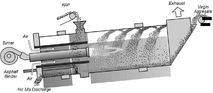
The components of the drum-mix plant are shown in Figure 42.
Source: Astec Industries
Figure 42. Typical Drum Mixer Layout
Individual aggregates are deposited in the cold-feed bins, from which they are fed individually in designed proportions onto a cold-feed conveyor. An automatic aggregate weighing system monitors the amount of aggregate flowing into the drum mixer. The weighing system is interlocked with the controls on the asphalt binder storage pump and a continuous metering system, which draws binder from a storage tank and introduces it into the drum. The asphalt binder and aggregate are thoroughly blended while rotating in the drum. A dust collection system captures excess dust escaping from the drum and mixing chamber. From the drum, the mix is elevated by a metal slat conveyor to the top of a surge bin or storage silo where it stays until loaded in a truck, as described in Section 4.9.
4.6.3 Aggregate Feed
In a drum-mix plant, mix gradation and uniformity depend mostly on the cold-feed system. Hence, it is essential the aggregate be correctly proportioned prior to its entry into the dryer/mixing drum. The most efficient way to accomplish this is with a multiple-bin cold-feed system equipped with precision belt feeders for the control of each aggregate.
Under each bin is a variable-speed belt feeder, which drops the metered aggregate onto a main collection belt that runs under all the cold-feed bins. The collection belt then transports the proportioned aggregate material to the main cold-feed conveyor belt, which carries the aggregate to the drum mixer.
Most cold-feed conveyor belts are equipped with provisions to conveniently obtain representative samples of the full flow of material for gradation determination or for calibration. Such devices are usually installed at the end of the belt just prior to entry into the drum mixer. Devices are available that can be installed on the main belt to divert or collect accurate samples without stopping the belt (see Figure 43).
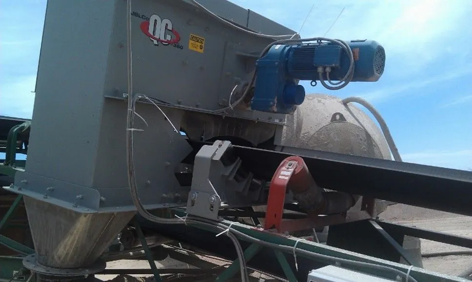
Source: Asphalt Institute
Figure 43. Conveyor Belt Sampling Device
Drum-mix plants require a continuous weighing system on the main cold-feed conveyor belt. As aggregate passes over the scale, they are continuously weighed and monitored by the hot-plant control system. No material should be diverted from or added to the conveyor belt after it passes the belt scale.
It is important to understand that the aggregate is weighed on the belt before drying. The total moisture content of the material entering the plant must be known so the asphalt pump can meter in the correct quantity of asphalt binder.
The moisture content of the cold-feed aggregate should be checked before beginning each day’s operation and again around mid-day. If the moisture content is believed to vary during the day, it should be checked more frequently. Some plants have moisture sensing devices that can sense changes in moisture content, coupled with the control system that compensates for moisture changes automatically.
4.6.4 Asphalt Binder Control with a Drum Mixer
Asphalt binder control in a drum mixer operation is done continuously. The asphalt binder is measured through a calibrated meter relative to aggregate flow after it has been corrected for moisture content and then combined with the aggregate in the mixing area of the drum.
The asphalt binder is measured through a calibrated meter relative to aggregate flow after it has been corrected for moisture content and then combined with the aggregate in the mixing area of the drum.
The asphalt binder content is interlocked to the aggregate flow. The monitoring system notes changes in the weight of aggregate over the belt scale and adjusts the asphalt binder flow to compensate for these changes.
The binder supply line runs continuously to keep pace with the aggregate weighbridge to deliver the proper ratio of binder in the mixing chamber. To confirm the metering system output is correct requires frequent verification of calibration or recalibration.
Taking a drum-mix plant offline to perform a calibration test can be very costly and time-consuming. Inline calibration tanks (see Figure 44) are an efficient way to calibrate asphalt metering systems without the downtime and risk associated with using the conventional tanker truck method.
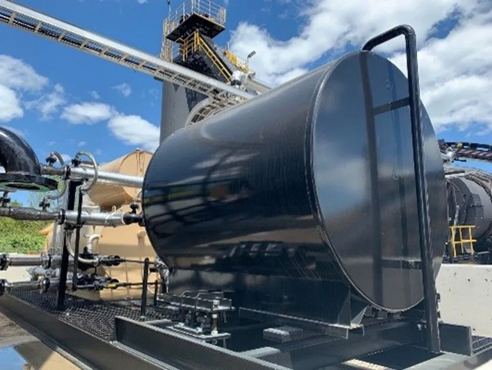
Source: ALmix Industries
Figure 44. Stationary Asphalt Binder Calibration Tank
4.6.5 Aggregate Flow
Aggregate enters the primary zone of the drum, where the burner dries and heats it. The aggregate then moves to a secondary zone, where asphalt binder is added and the two are thoroughly blended. The mixture of hot asphalt binder and the moisture released from the aggregate produces a foaming mass that traps much of the fine material (dust) and coats the larger particles. It is important that the aggregate in the drum not only rotate with the revolving motion of the drum but also spread out sufficiently to make heating and drying of all particles quick and efficient. Drum mixers are equipped with specially designed flights to create a “veil” or curtain of aggregate at appropriate parts of the drum for obtaining maximum drying and minimizing exhaust gas temperatures.
4.6.6 Binder Flow
Asphalt binder is pumped from the binder storage tank and enters the mixing drum at the appropriate point in accordance with the plant design. When the asphalt binder is added into the drum, it is pumped into the drum’s lower end at about the same location that the mineral filler and/or baghouse fines are introduced. Adding asphalt binder and dust in close proximity allows the binder to trap a good portion of the fines and coat them before they are picked up by the high-velocity exhaust gas stream. The exhaust gases are passed through a dust collection system where any of the remaining dust is trapped and removed to meet emission requirements, as discussed in Section 4.7.
4.6.7 Recycling with a Drum-Mix Plant
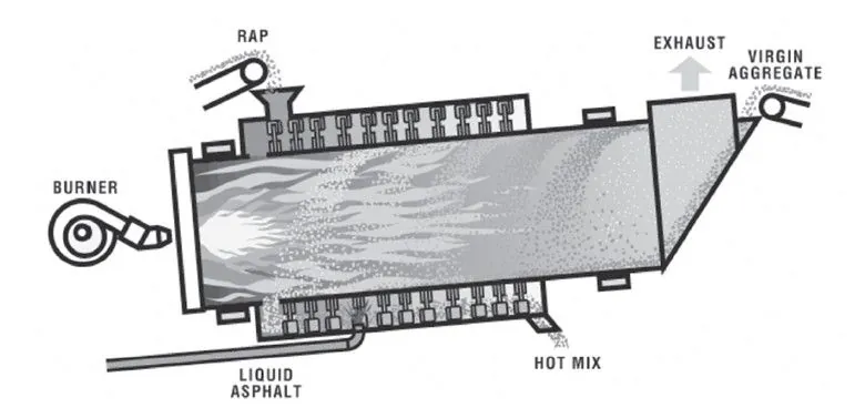
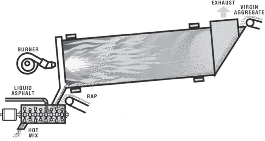
The introduction of RAP into a drum-mixing operation is quite different from the methods used in a batch plant. To minimize RAP binder damage and emission-control problems, it is necessary to add RAP via a split-feed system. In a split-feed system, new aggregate enters the drum in one location, and the RAP enters the system downstream, where it is not in direct contact with the burner flame. Figure 45, Figure 46, and Figure 47 illustrate typical RAP entry points for several types of drum-mix plants.
Source: Asphalt Institute
Figure 45. Counterflow Drum-Mix Plant
Source: Asphalt Institute
Figure 46. Unitized (Double-Barrel) Drum-Mix Plant
Source: Asphalt Institute
Figure 47. Counterflow Dryer with Separate Continuous Mixer
As mentioned in Section 4.5.10 regarding RAP in batch plants, a drum mixer also requires superheated virgin aggregate to transfer heat into the RAP and remove any moisture present. These conditions can present significant obstacles that can limit the maximum rate and amount of RAP mix that can be produced.
Normally, if 20 percent or less RAP is incorporated into a recycled mix and a split-feed system is used, minimal emission-control issues arise. As the percentage of RAP rises and the moisture content of the RAP increases, there is a greater potential for heat transfer and emission problems. A typical drum-mix plant requires carefully controlled production conditions to incorporate over 50 percent RAP in a recycled mix without major emissions and heat transfer issues.