AAPTP
  • Small
  • Medium
  • Large
  • Small
  • Medium
  • Large
  • Home
  • Handbook
    • Asphalt Paving Handbook
    • Videos
    • Figures
    • Tables
  • Checklists
  • Abbreviations
  • About
  • HOME
  • Handbook
    • Asphalt Paving Handbook
    • Videos
    • Figures
    • Tables
  • CHECKLISTS
  • ABBREVIATIONS
  • About
1. Introduction
  • 1.1 Handbook Purpose and Organization
  • 1.2 Airfield Paving
  • 1.3 Asphalt Mixtures Defined and Classified
  • 1.4 Workmanship
  • 1.5 Certification and Accreditation Programs
2. Project Organization
  • 2.1 Introduction
  • 2.2 Project Documents
  • 2.3 Preconstruction Conference
  • 2.4 Ongoing Communication
  • 2.5 Ongoing Records
  • 2.6 Safety
3. Asphalt Materials and Mix Design
  • 3.1 Introduction
  • 3.2 Asphalt Binder: Grading Systems And Properties
  • 3.3 Aggregate Characteristics And Properties
  • 3.4 Mixture Volumetrics
  • 3.5 Asphalt Mix Properties
  • 3.6 Additives
  • 3.7 Mix Design Procedures
  • 3.8 Laboratory Versus Plan-produced Mixes
  • 3.9 Summary
4. Mix Production
  • 4.1 Introduction
  • 4.2 Material Storage and Handling
  • 4.3 Aggregate Cold Feed
  • 4.4 Aggregate Drying and Heating
  • 4.5 Batch Plants
  • 4.6 Drum and Continuous Plants
  • 4.7 Emission-Control System
  • 4.8 Temporary Mixture Storage
  • 4.9 Weighing and Loadout
  • 4.10 Safety
  • 4.11 Troubleshooting and Checklists
5. Surface Preparation
  • 5.1 Introduction
  • 5.2 Base Preparation for New Asphalt Pavements
  • 5.3 Asphalt Surface Preparation for Asphalt Overlays
  • 5.4 PCC Surface Preparation For Asphalt Overlays
  • 5.5 Tack Coat
  • 5.6 Summary
6. Mixture Delivery
  • 6.1 Introduction
  • 6.2 Planning
  • 6.3 Truck Types
  • 6.4 Proper Truck Loading
  • 6.5 Hauling Procedures
  • 6.6 Unloading the Mix
  • 6.7 Tracking Quantities
7. Mix Placement
  • 7.1 Introduction
  • 7.2 Tractor Unit
  • 7.3 Screed Unit
  • 7.4 Grade Control
  • 7.5 Layer Thickness
  • 7.6 Establishing Paver Speed
  • 7.7 Related Paving Operations
  • 7.8 Best Practices Checklists
8. Compaction
  • 8.1 Introduction
  • 8.2 Definitions
  • 8.3 Rollers
  • 8.4 Factors Affecting Compaction
  • 8.5 Compaction Variables Under The Operator’s Control
  • 8.6 Determination of Rolling Pattern
  • 8.7 Roller Checklists
9. Joint Construction
  • 9.1 Introduction
  • 9.2 Transverse/Construction Joints
  • 9.3 Longitudinal Joints
  • 9.4 Echelon Paving and Rolling
  • 9.5 Unconventional Longitudinal Joint Methods
10. Segregation
  • 10.1 Introduction
  • 10.2 Recognizing Physical Segregation, Causes, and Solutions
  • 10.3 Four Stages Where Segregation Can Originate
  • 10.4 Thermal Segregation
  • 10.5 Confirming and Quantifying Segregation
11. Quality Assurance
  • 11.1 Introduction
  • 11.2 Definitions
  • 11.3 General Types Of Specifications
  • 11.4 Quality Control Plan
  • 11.5 Sampling Methods
  • 11.6 Quality Control At The Plant
  • 11.7 Quality Control In The Field: Placement And Compaction
  • 11.8 Acceptance
12. Mat Problems
  • 12. Mat Problems
  • 12.1 Surface Waves
  • 12.2 Tearing (Streaks)
  • 12.3 Nonuniform Texture
  • 12.4 Screed Marks
  • 12.5 Screed Responsiveness
  • 12.6 Surface (Auger) Shadows
  • 12.7 Poor Precompaction
  • 12.8 Joint Problems
  • 12.9 Checking
  • 12.10 Shoving And Rutting
  • 12.11 Bleeding And Fat Spots
  • 12.12 Roller Marks
  • 12.13 Poor Mix Compaction
  • 12.14 Other Pavement Problems
Appendix
  • AAPTP Airport Asphalt Videos

4. Mix Production

4.7 Emission-Control System

The high-speed air flowing through the dryer that carries away exhaust gases also removes small, dust-sized particles (smaller than 0.075 mm) from the aggregate blend. Because this dust is part of the mixture design, it must be captured and returned to the mix being produced. Removing the dust from the exhaust stream with high-efficiency emission-control equipment prevents plant-produced dust emissions from exceeding local, State, and Federal air quality limits.

4.7.1 Basics of Dust Collection

The amount of airborne dust is a function of the material being dried, the velocity of the air in the dryer, and the location of the binder injection point that captures the smaller particles.

The emission-control system on most asphalt plant facilities generally consists of primary and secondary dust collectors. The dust collectors are situated downstream of the dryer and filter the air that exits the drum.

4.7.2 Primary Collectors

The purpose of the primary collector is to collect and remove the larger dust particles contained in the exhaust gas stream. The typical primary collectors are called the knockout box or the cyclone collector.

The knockout box is the simplest type of primary collector (see Figure 48). The exhaust gas flows through an expanded chamber, causing the airspeed to decrease. The chamber also contains plates to cause a change in the direction of airflow. The speed reduction and direction changes cause the larger dust particles to drop out of the airstream to the bottom of the box, where they are reintroduced in the dryer.

Figure 48. Knockout Box Returning Coarse Fines to the Dryer

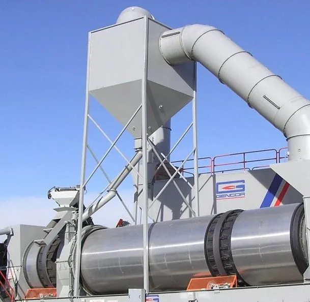
Source: Gencor Industries
Figure 48. Knockout Box Returning Coarse Fines to the Dryer

Cyclone collectors are more efficient than knockout boxes and operate on the principle of centrifugal separation. The exhaust stream circulates inside the collector (shown in Figure 49), and particles hit the outside wall and drop to the bottom of the cyclone. Speed and directional changes also assist as the exhaust is discharged through the top of the collector. The fines collected at the bottom of the cyclone are picked up by a dust-return auger and may be returned to the plant or removed.

Figure 49. Cyclone Collector Returning Coarse Fines to the Dryer

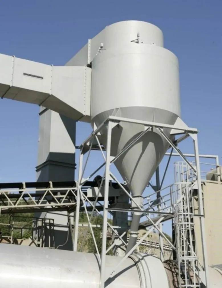
Source: Asphalt Institute
Figure 49. Cyclone Collector Returning Coarse Fines to the Dryer

4.7.3 Secondary Collectors

The purpose of the secondary collector is to filter out the finest dust particles. The most common type of secondary collector is referred to as a baghouse. A baghouse (see Figure 50) is a large metal housing containing hundreds of heat-resistant fabric filter bags. A typical unit may contain as many as 800 bags. It operates on a principle similar to a vacuum cleaner. The dust-laden exhaust gases are pulled through the filter bags supported on long wire cages to prevent collapse. The dust is trapped on the outside of the bag as the air passes through the filter cloth to the clean air side, effectively cleaning all the dust from the exhaust stream. When properly operated, baghouses can be very efficient, removing over 99 percent of the dust from the dryer exhaust.

Figure 50. Baghouse Dust Collector

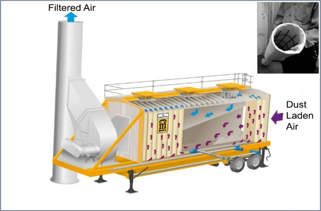
Source: CMI Roadbuilding, Inc.
Figure 50. Baghouse Dust Collector

Dust continuously collects on the outside of the fabric filter while the dryer is in operation. Periodically, a pulse of air is passed through the bag in the opposite direction, causing the bag to flex in reverse. The collected dust drops off the bag and falls to the bottom hopper of the baghouse. This collected dust can either be returned to the mix production process or removed. When dust is returned to the plant process, certain operational practices are important to keep the dust return uniform and consistent. Non-uniform introduction of baghouse fines back to the plant can cause erratic volumetric test results. Refer to Section 4.3.3.

Previous Section
Next Section

© National Asphalt Pavement Association (NAPA). All rights reserved|Privacy Policy

6406 Ivy Lane, Suite 350 Greenbelt, Maryland 20770-1441

|888-468-6499
  • LinkedIn
  • Facebook
  • Twitter
  • YouTube
  • Instagram
Information

There are no items associated with the selected chapter.