7. Mix Placement
7.3 Screed Unit
Watch Video
The screed unit, which is towed by the tractor unit, establishes the thickness of the asphalt layer and provides the initial texture to the new surface. In addition, through its weight and vibratory action, the screed imparts the initial density into the material being placed.
The concept of the free-floating paver screed was developed in the early 1930s. The design allows the paver screedto average out changes in grade or elevation experienced by the wheelbase (rubber tires or crawler tracks) of the tractor unit. The floating screed concept is employed on all modern asphalt pavers in use today.
Screeds are classified into two basic types: fixed-width and hydraulically extendable. A fixed-width screed consists of one screed frame that is typically 8 or 10 ft wide. Fixed, bolt-on extensions, shown in Figure 92, must be attached to increase the paving width. Fixed-width screeds are less complex and more rigid, which makes it easier to create uniform layer density from edge to edge when paving wide widths.
Source: Asphalt Institute
Figure 92. Fixed-Width Screed with Vibratory Bolt-On Extensions
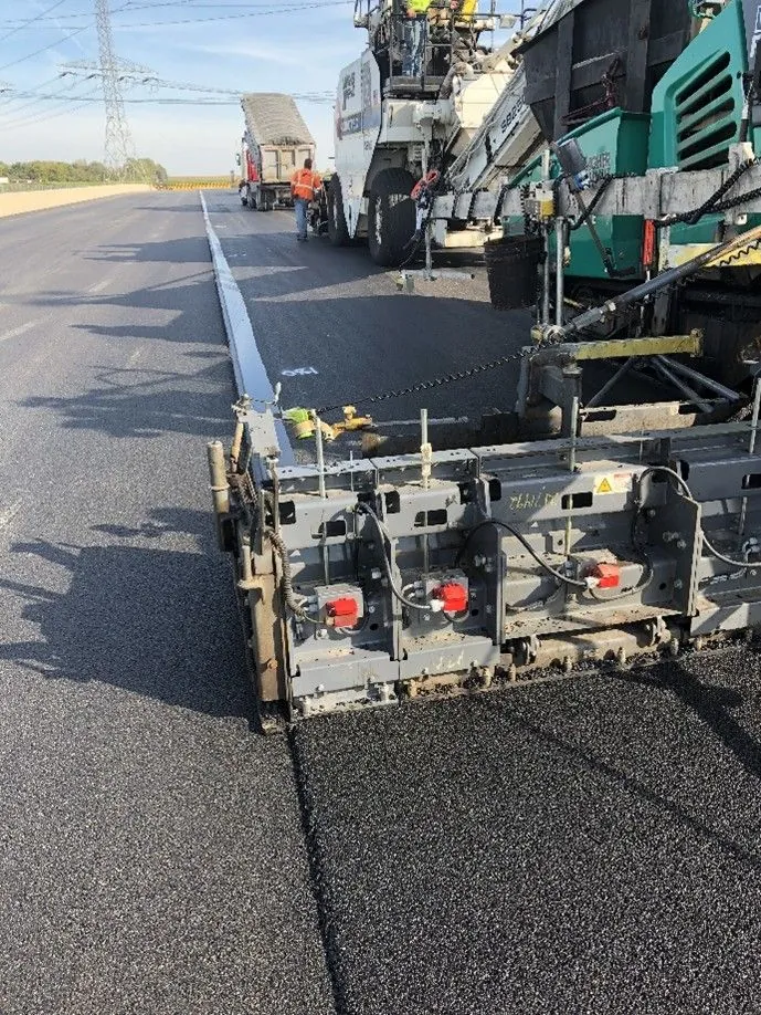
Hydraulically extendable screeds are the most common screed type in use today. Continuously variable widths up to twice the width of the main screed provide increased versatility. Hydraulic screed extensions, shown in Figure 93, are able to pave variable-width pavement sections while the paver is in motion. Lane bump-outs, tapered lanes, and radius sections are just a few examples.
All screed extensions, either fixed or hydraulically extended, must be properly adjusted to place an asphalt mat to the desired thickness, providing a uniform surface across the top of the mat.

Source: National Asphalt Pavement Association
Figure 93. Extendable Screed Paver
Hydraulic screed extensions are mounted in one of two ways, either in front of or behind the main screed. Front-mounted extensions move in and out in front of the main screed. Front-mounted screeds can be retracted more easily than rear-mounted extensions. This is because the front-mounted screeds can displace the head of the mix into the main auger chamber as they are retracted. Rear-mounted screeds must deal with the compression of the paving mix against the end of the main screed as they are retracted. Hence, front-mounted screeds are more often seen on urban-type projects, and rear-mounted screeds are preferred by crews that pave mainline highways and airfield projects that require less frequent width changes.
7.3.1 Tow Points
The screed unit is attached to the tractor unit at only one point on each side of the paver. This point, shown in Figure 94, is called the tow (or pull) point. The tow points are pin-type connections that allow the leveling arms (also called side arms, pull arms, or tow arms) of the screed to freely rotate or pivot around those points. The tow points are mounted to the end of a hydraulic cylinder that is fixed to the tractor frame. The height of the tow points can be manually adjusted or controlled automatically by the paver. Automatic screeds are thoroughly discussed in Section 7.4.
7.3.2 Line of Pull
The line of pull refers to the angle at which the screed is pulled forward. A smoother pavement surface is generally placed when the towing force is applied parallel to the final surface that is being placed. Thus, the elevation of the tow points should be set in relation to the thickness of the mat being constructed. Generally, thin lifts of HMA require a lower initial tow point setting, while thick lifts of mix require a higher initial setting.
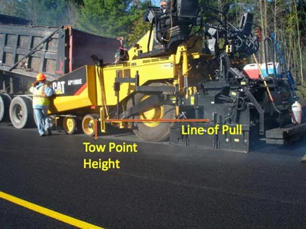
Source: University of Idaho Visual Productions
Figure 94. Tow Point and Line of Pull
For a relatively thin mat, if the tow point setting is extremely high, the towing forces are applied at an upward angle that increases the lift forces acting on the screed. To maintain a given thickness of material, the angle of attack of the screed must then be decreased to compensate for the increased lift. In this condition, the screed runs at a slightly nose-down angle of attack. Only the front portion of the screed is then compacting and finishing the HMA being placed; the result is poor mat texture and extreme wear on the front portion of the screed plate. In addition, when the paver stops, the screed can have a tendency to rock or teeter as the tractor relaxes the tension on the screed. This may increase the amount of settling of the screed and introduce bumps into the mat.
For a relatively thick mat, if the tow point setting isextremely low, the towing forces are applied at a downward angle that decreases the lift forces applied to the screed. To maintain a given thickness of HMA, the angle of attack of the screed must then be increased to compensate for the decreased lift. In this condition, the screed runs with the rear portion of the screed bearing the majority of the compacting and finishing pressure. This causes poor mat texture and extreme wear on the rear portion of the bottom of the screed plate. Increased control of the forces applied to the screed is gained by setting the tow points in relation to the thickness of the mat being placed.
The floating screed principle is able to operate under manual control. When operated under manual control, it is important that the tow points on both sides of the tractor are at the same level above the base layer. The position of the tow points can be altered by raising or lowering the tow point mounts. For most asphalt mixtures, the tow points are positioned near the middle of the tow point range of movement. For some asphalt mixtures, such as those that are very stiff or very tender, it may be advantageous to raise or lower the elevation of the tow points to improve the texture of the mat being placed.
7.3.3 Forces Acting on the Screed
The ability of a free-floating screed to function is the result of the delicate balancing of forces that react on the screed (see Figure 95). The forces on the screed must be in equilibrium (the sum of all forces equal to zero) for the free-floating screed to remain suspended in the mix as it is towed by the tractor unit. The forces exerted on the front of the screed and below the screed are counteracted by the weight of the screed and the angle of attack. When a change in any one force occurs, the screed will rise or fall until it reaches a new equilibrium, and the thickness of the mat being placed will change accordingly.
The forces on the screed must be in equilibrium (the sum of all forces equal to zero) for the free-floating screed to remain suspended in the mix as it is towed by the tractor unit.
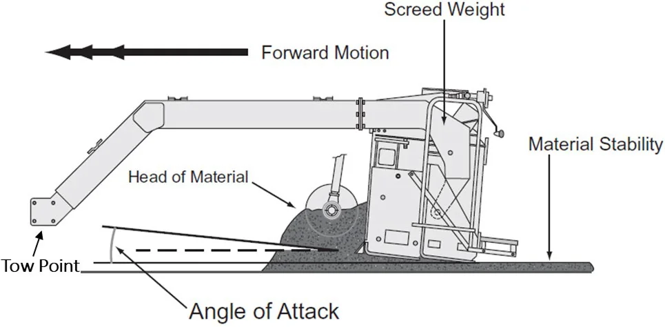
Source: Asphalt Institute
Figure 95. Elements That Impact Screed Forces
Many forces impact the screed. It is important to understand those forces that are most easily managed in the field: the angle of attack, paver speed, head of material, and mixture properties (temperature).
7.3.3.1 Angle of Attack
The forward end of the screed tow arms attaches to pivot points at the tow point on the paver. The tow point pivot is always free to rotate as the screed is towed through the mix. There is another pivot at the rear of the tow arms where it attaches to the screed. This screed pivot is locked into position by the thickness control device (screw) located on the screed. The position of this locking screw establishes the angle of attack.
The pitch of the angle of attack contributes significantly to the upward force on the screed and allows the free-floating screed to function. If no other force acting on the screed changes, an increase in the angle of attack will increase the upward component of force acting on the screed. Decreasing the pitch reduces the upward force on the screed. The screed elevation will respond to changes of force until the forces exerted on the screed return to equilibrium.
The tow point elevation and the angle of attack should be adjusted so that there is uniform pressure on the bottom of the screed plate (from front to back) while paving at the desired thickness. If the angle of attack is too low, there will be excessive pressure and wear on the nose of the screed; if too high, that pressure and wear will be on the tail of the screed. Both conditions can result in nonuniform texture problems and roughness in the finished mat surface.
7.3.3.2 Paver Speed
The upward force exerted on the screed changes as the speed of the paver increases and decreases. As the speed of the paver increases, the upward force created by the material passing under the screed is reduced. When this force is reduced, the weight of the screed causes it to fall. If the tow point remains unchanged, the falling screed rotates about the tow point pivot and increases the angle of attack until equilibrium is reached at a new elevation (thinner mat). Conversely, when the paver speed decreases, the friction is increased, creating more force against the screed. The screed rises until the decreasing angle of attack and weight of the screed reach equilibrium with the increased force of the mix. Because the speed of the paver has a major effect on the angle of attack of the paver screed, it is good paving practice to keep the speed as consistent as possible during laydown operations.
Ideally, the speed of the paver should be matched to the production rate of the asphalt plant. Assuming the paving day length is the same as the plant production day, the ideal paving speed is when the paver consumes the mix at the same rate it is produced by the plant.
As an example, if an asphalt plant is producing 300 tons per hr for 10 hrs, it would produce 3,000 tons per day. If the pavement being placed requires 1,000 tons per mi, the plant will produce a 3-mi (15,840 ft) length of pavement. If that length is to be paved in 10 hrs (600 min), the theoretical paving speed would be 15,840 ft divided by 600 min, which equals 26.4 ft per min.
Should the pavement being placed require 1,500 tons per mi, the length would be 2 mi per 10-hr day. In this case, the paving speed is 10,560 ft divided by 600 min, which equals 17.6 ft per min. Every project will be different, but consistent, nonstop paving should be the goal. Section 7.5 provides an in-depth discussion on calculating yield.
As noted previously, to achieve the smoothest possible mat behind the paver screed, it is essential to keep the paver always moving at a constant speed. Running the paver faster than necessary to place all the delivered mix and then stopping to wait for the next haul truck to arrive at the paving site will diminish the quality of the mat.
When the paver needs to be stopped, it should be stopped as quickly and smoothly as possible before the level of mix in the hopper is drawn down below the top of the flow gates or the tunnel openings. This will keep the head of material in front of the screed constant while the effect of the change in the paver speed on the angle of attack of the screed is minimized because of the rapid speed change. The paver operator should return the laydown machine to the desired paving speed as quickly as possible to minimize the effect of the change in paver speed on the angle of attack. It has been found that the “rapid stop, rapid start” procedure for stopping the paver provides for good mat smoothness and consistent mat thickness.
When the paver needs to be stopped, it should be stopped as quickly and smoothly as possible before the level of mix in the hopper is drawn down below the top of the flow gates or the tunnel openings.
It is good paving practice for the paver to remain in one position, with the hopper as full as possible and the head of material constant, until additional mix arrives. If a long delay is expected, consideration should be given to constructing a transverse joint.
7.3.3.3 Head of Material
The head of material is the amount of asphalt mix in the auger chamber that exerts force against the screed. When the head of material changes, the net force acting on the screed also changes. As the forces acting on the screed change, the screed must come to a new angle of attack to compensate for the change in force acting on it.
The head of material in the auger chamber is directly affected by the operation of the slat conveyors and augers on each side of the paver. When the slat conveyors and augers are operating, the mix is pulled from the paver hopper, through the tunnel, and is distributed across the front of the screed by the augers. If the flow of material and paver speed is relatively constant, the head of material pushing against the screed remains relatively constant as well, and the mat being placed has a smooth and consistent texture (see Figure 96).
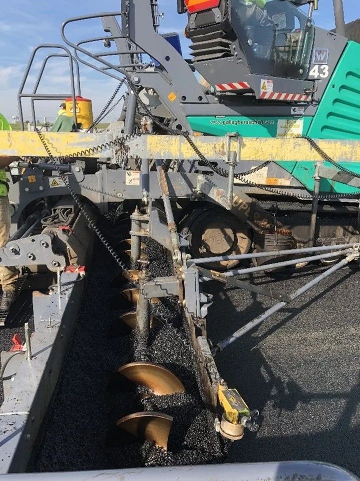
Source: Asphalt Institute
Figure 96. Paving Wide with a Uniform Head of Material
If the head of material is allowed to vary, the screed moves up and down in reaction to the forces acting on it. When the amount of mix being carried by the augers is decreased because the slat conveyor and auger systems are running low or shut off, the screed moves downward, thus reducing the thickness of the mat behind the screed. As the slat conveyor and auger systems come on, more mix is carried back to the augers and across the front of the screed. This increases the force on the screed and causes it to rise to a new elevation, resulting in a thicker mat. Thus, it is very important to regulate the amount of mix in front of the screed since a consistent head of material in front of the screed is associated with a consistently smooth mat behind the paver.
7.3.3.4 Mixture Stiffness
Another factor that affects the balance of forces on the screed is the temperature or consistency of the mix. If a cold load of material is deposited in the paver hopper, the stiffer mix increases the force acting on the screed and causes the screed to rise, increasing the thickness of the layer placed. If, on the other hand, a hot load of mix is delivered to the paver, the decrease in viscosity of the binder material reduces the stiffness of the mix and reduces the force exerted on the screed. This situation causes the screed to fall and reduces the layer thickness. The mixture type can also play a role in the amount of force exerted by the head of material against the screed. For example, a coarse mix with a highly modified asphalt binder is stiffer than a sandy mixture with an unmodified binder.
7.3.4 Thickness Controls
Watch Video
As noted earlier, the screed is attached to the leveling or tow arms on each side of the paver through pivot points. The thickness control mechanism, usually either a crank or a handle, allows the screed to be moved or rotated around a pivot point. The key to the leveling action of the screed is the attachment to the tractor unit at tow points that pivot. This allows the screed to react to the forces exerted on it and remain in an equilibrium position. As the mix passes under the screed plate, the screed floats through the mix, establishing the mat thickness and the texture of the surface while providing the initial compaction of the mat.
The key to the leveling action of the screed is the attachment to the tractor unit at two points that pivot. This allows the screed to react to the forces exerted on it and remain in an equilibrium position.
7.3.4.1 Changing the Thickness Control Screws
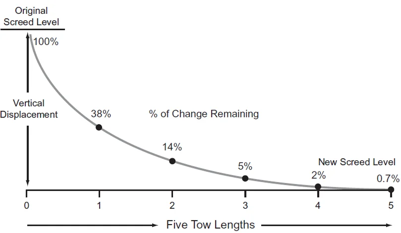
For a constant position of the tow points (the tractor unit running on a level surface and without automatic screed controls), altering the setting of the thickness control screws changes the angle of attack of the screed and the forces acting on the screed. This in turn causes the screed to move up or down to a new elevation as the paver moves forward, thus altering the thickness of the mat being placed. The reaction of the screed to changes in the angle of attack is not instantaneous. There is a lag in the reaction that allows the screed to average out variations in the input forces acting on it.
Figure 97 shows the reaction time of the screed when a change is made to the angle of attack, either at the screed or at the tow points. It takes approximately five times the length of the tow arms for the screed to complete 99 percent of the change, up or down, to the desired new elevation. This means that if the length of the tow arms is 10 ft (3 m), the paver must move forward at least 50 ft (15 m) before a thickness-control screw change is completely carried out by the paver screed. The same applies if the angle of attack of the screed is changed by the automatic screed controls changing the height of the tow points.
Source: Asphalt Institute
Figure 97. Distance Required for the Screed to Reach Equilibrium
It is essential for the screed operator to be aware of this lag in the reaction time of the screed. If a second change in the setting of the thickness control crank is made before the first change has been accomplished, the first change will never be completed, and it will still take an additional five times the length of the leveling arm for the second thickness change to be carried out. For this reason, continual changes in the setting of the thickness control devices are likely to be highly detrimental to the pavement smoothness.
Because of the delayed reaction time of the screed, a single mat-depth measurement should not be used to justify a change in the angle of attack of the screed. Indeed, even two or three measurements should not be averaged to determine whether a change in the setting of the thickness control cranks is needed. If the uncompacted thickness of the mat is to be checked using a depth gauge, the mat thickness behind the screed should be measured at least five times at 6-ft (2-m) intervals longitudinally. A better way to periodically check yield is to determine the distance 10 truckloads of mix should cover, based on the width and uncompacted thickness being laid. This distance is then compared with the length of pavement the paver has actually placed using the same number of tons of mix. If the distance covered is significantly different than it should have been, the setting of the thickness control cranks should be changed to slightly adjust the angle of attack of the screed to achieve the desired result.
Continual changes in the setting of the thickness control devices are likely to be highly detrimental to the pavement smoothness.
7.3.4.2 Changing the Tow Point Elevation
The above discussion also applies when there is a change in the height of the tow points on the tractor unit. If the height of the tow points moves, the change in their elevation translates to a change in the angle of attack of the paver screed. The paver must still move forward for approximately five times the length of the leveling arm on the machine for the screed to react to the change in the location of the tow points and move up or down to the new elevation. As a roadway is being paved without the use of automatic grade and slope controls, the tractor unit moves upward and downward in response to the grade of the underlying pavement. The vertical movement of the tractor translates into vertical movement of the tow points on the sides of the paver. Each time the tractor goes over a hump or into a dip in the existing pavement surface, the elevation of the tow points changes. This in turn alters the angle of attack of the screed, causing the amount of material flowing under the screed to be decreased or increased. The fact that it takes five times the length of the leveling arm before the screed reacts completely to a change in the location of the tow points allows the screed to reduce the thickness of the asphalt mix being placed over the high places in the existing surface and to place more mix in the low spots of the roadway. It is this averaging or leveling action that forms the basis for the floating screed principle discussed earlier.
The use of automatic paver controls, discussed in the next section, allows the paver to construct a smoother pavement by keeping the location of the screed tow points constant, relative to a predetermined reference, as the tractor unit moves up and down vertically in response to small changes in the grade of the underlying pavement surface. By maintaining the tow points at a constant relationship to the predetermined reference while the tractor moves vertically, the force on the screed remains constant, and the angle of attack of the screed is consistent in comparison with the reference. This allows the screed to carry out the leveling action needed over a longer reference length to reduce the roughness of the existing surface through the application of the new asphalt layer.
7.3.5 Screed Strike-Offs
The screed on some pavers is equipped with a plate on its front edge called a strike-off (or sometimes a prestrike-off). The purpose of this device is to control the amount of mix allowed to pass under the nose of the screed, thereby affecting the screed’s angle of attack. The strike-off is also used to reduce the wear on the leading edge of the screed.
When a strike-off is present, its position is important. If the strike-off is set too high, extra material is fed under the screed, causing the screed to rise. The resulting increase in the mat thickness must be overcome by manually reducing the angle of attack of the screed using the thickness-control cranks. This in turn causes the screed to pivot around its pivot points and ride with a lower angle of attack. Rapid wear of the screed nose plate results because the front portion of the screed is doing most of the compacting and finishing. This often leads to inconsistent mat texture. In addition, the screed settles more when the paver is stopped between truckloads of mix because the screed’s weight is carried only on its front.
When the strike-off is set too low, the thickness of the lift is reduced because not enough mix is allowed to pass under the screed. To maintain the proper mat thickness, the angle of attack of the screed must be altered, causing the screed to ride on its tail in a slight nose-up attitude. This increases the wear on the back edge of the screed and reduces the compactive effort applied by the screed. It also causes the screed to settle more whenever the paver is stopped because of the concentration of the screed’s weight on a smaller surface area.
The exact location of the strike-off depends on the make and model of paver being used and the thickness being placed. For relatively thin layers of pavement (1 inch [25 mm] thick or less), the strike-off is usually placed lower than when thicker lifts of mix are being placed. Similarly, for thick lifts of asphalt pavement (greater than 2 inches [50 mm]), the strike-off assembly is usually raised slightly above the normal position. In general, the strike-off is located in the range of 3/16 to 1/2 inch (5 to 13 mm) above the bottom plane of the main screed plate. No compaction of the mix occurs under the strike-off.
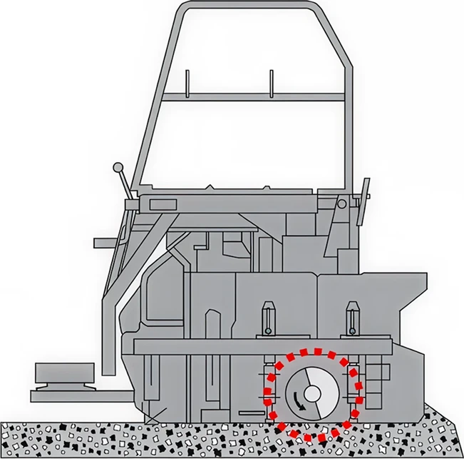
7.3.6 Vibratory Screeds
The amount of compaction imparted to the asphalt mix by the screed is a function of many variables. The properties of the mix itself are important—its stiffness, its temperature, and the amount of asphalt binder and moisture it contains all affect the ability of the screed to densify the mix. The degree of compaction achieved is also affected by the amount of bearing pressure applied to the mix by the screed, as well as the thickness of the mat passing under the screed.
Screed vibration is achieved using a rotating shaft and counterweight. Two elements of the vibrating screed (see Figure 98) contribute to the degree of compaction achieved: the frequency of vibration (number of vibrations per minute) and the amplitude (amount of force) imparted by the screed. Increasing the revolutions per minute of the shaft will increase the frequency of the vibration and the compactive effort. Typically, the vibrators should be used at the highest frequency setting to obtain the maximum compactive effort.
The applied amplitude is determined by the location of the eccentric weights on the shaft. The position of the eccentric weights can be altered to increase or decrease the amount of compactive effort applied. Typically, the amplitude setting selected is related to the thickness of the mat being placed—lower amplitude for thinner lifts and higher amplitude for thicker lifts.
Vibrators should be used at the highest frequency setting to obtain the maximum compactive effort.
The density achieved by the paver screed is also a function of the speed of the paver. As the paver moves faster, the screed dwells for less time over any given point in the new mat, and the amount of compactive effort applied by the screed decreases. It can be expected that approximately 70 to 90 percent of the theoretical maximum density (TMD) of the HMA will be obtained when the mix passes out from under the paver screed.
Source: Asphalt Institute
Figure 98. Vibrating Screed
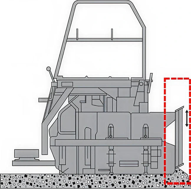
7.3.7 Tamper Bars
Some screeds have vertical tamper bars at their leading edge (see Figure 99) that serve a dual purpose: they strike off the mixture and direct the mix under the screed. This can often produce a greater initial density than a vibratory screed.
At higher paving speeds, the tamper-bar system does not have enough time to tuck the material under the screed. The speed at which this becomes an issue varies depending on mix properties and lift thickness. This can result in a surface texture where the surface aggregates appear to be dragging along behind the screed or even a torn asphalt pavement surface. Some pavers have screeds with dual tamper bars—a second line of tamper bars behind the first. While a second tamper bar may add additional initial density and allow for faster paving speeds, it makes the screed mechanically more complicated and harder to maintain.
To operate properly, tamping bars must be adjusted and maintained according to the manufacturer’s recommendations. Tamper bars typically protrude below the leading edge of the screed just enough to catch a fingernail on it, or 1/64–1/32 inch (0.4–0.8 mm). An agency-approved release agent should be applied at the end of each shift to keep bars from seizing up at the start of the next paving cycle.
Source: Asphalt Institute
Figure 99. Tamping Bar Screed
7.3.8 Screed Heaters
The screed is equipped with two or more heaters, or burners, depending on the age and model of the paver. The purpose of the heaters is to preheat the plate on the bottom of the screed to the temperature of the mix being laid. The screed should be heated before paving operations begin and at any time the screed has been raised out of the mix for an extended period. The screed should be at nearly the same temperature as the asphalt material passing under it to ensure that the mix does not stick to the screed plate and tear, imparting a rough texture to the mat. A properly heated screed provides for a more uniform mat surface texture and a more consistent mat thickness. To preheat the screed, the heaters are normally operated for a period of 10 to 20 min before the laydown operation begins. Care should be taken to avoid overheating, which can cause permanent warping of the screed plate. Electric screed heaters tend to provide more uniform heating of the screed. Usually within 10 minutes after paving has begun, the temperature of the screed plate has increased to the point at which it can generally be maintained by the temperature of the mix passing under it. Thus, the heaters are not needed and are shut off. A major misconception is that the heaters can be used to heat up cold material as it passes under the screed. This is simply not true. Only the very top surface of the mix is warmed up slightly, while the bottom of the screed may be superheated to the point of warping. For the same reasons, the screed heaters should not be used to increase the temperature of the mix sitting under the screed for a period of time while awaiting the arrival of the next haul truck.
A major misconception is that the heaters can be used to heat up cold material as it passes under the screed
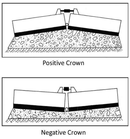
7.3.9 Screed Crown
When paving crown into the pavement cross section (such as the centerline of the pavement), the screed can be angled at its center to provide the correct slope (see Figure 100). The amount of crown that can be introduced into the screed varies with the width of the screed and with the make and model of the equipment.
The crown is typically adjusted using a turnbuckle device to flex the bottom of the screed and impart the desired degree of crown. When rigid extensions are used, the cross-sectional profile of the mat can be altered at any of the points where the extensions are joined (such as when paving a different shoulder slope). If a hydraulically extendable screed is being used with the paver, the crown can be introduced not only in the center of the screed, but also at the points between the screed and the hydraulic extensions.
Source: Asphalt Institute
Figure 100. Screed Crown
When paving flat sections (one lane at a time), some paver manufacturers recommend that the screed be warped slightly, from front to back in its center, to facilitate the passage of mix under the screed and to obtain a more uniform texture on the asphalt mat. This process involves setting the lead crown on the screed slightly above the tail crown on the screed. In general, there should be more lead than tail crown, but the amount of difference depends on the make of paver and the type of screed. Normally the lead crown setting is 1/32 to 3/16 inches (1 to 5 mm) greater than the tail crown setting, with 1/8 inches (3 mm) being the average difference between the crown settings. For hydraulically extendable screeds, some paver manufacturers do not recommend setting any amount of lead crown into the front edge of the screed.
Because of different recommendations for different makes and models of pavers, it is suggested that the manufacturer’s operation manual be consulted before the crown is set into the screed.