9. Joint Construction
9.2 Transverse/Construction Joints
Watch Video
9.2.1 At End of Paving Operation
When a paving operation is suspended in the middle of a project, whether overnight or for an extended period, a transverse construction joint is required.
For airfields, it is desirable for the paving at the end of the day to end at the area being paved, such as the end of a runway, to reduce the number of transverse joints, which will tend to increase smoothness and minimize FOD.
For airfields, it is desirable for the paving at the end of the day to end at the area being paved, such as the end of a runway, to reduce the number of transverse joints
When a transverse joint is required, it is important that the paver be run in normal fashion right up to the point at which the transverse joint will be located. The head of material in front of the screed should remain constant up to the location of the joint so the forces acting on the screed are constant and a consistent angle of attack is maintained.
A good practice is to locate the transverse joint at a point where the head of material in front of the screed is normal. It is a poor practice to run the hopper out of mix before the location where a transverse joint is to be built. When this is done, the amount of mix carried on the augers is reduced, as is the head of material in front of the paver screed, causing the screed angle to fall. The thickness of the mat will then gradually decrease leading up to the joint location. This will result in a low point on the new pavement surface.
When paving resumes, an almost vertical face is needed on the cold side of the joint. Creating that vertical face, whether the joint was temporarily opened to traffic or not, is discussed in the next section.
If opened to traffic, the transverse joint needs to provide a safe, smooth transition for vehicles dropping from the level of the new surface down to the existing surface. The easiest way to do this is to build a temporary wedge of material to ramp traffic down to the underlying surface. This wedge is removed before paving operations resume.
9.2.1.1 Temporary Ramp for Traffic
There are three methods paving contractors can employ for properly building the sacrificial wedge:
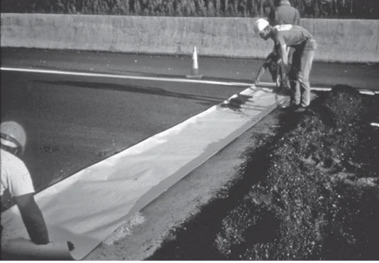
- Stop the paver and lift the screed over the head of material in the auger area. Then separate the excess material by shoveling a transverse trench in the fresh mix on the downstream side of the joint. Push back the face of the joint line with a lute or rake to make a sharp vertical edge on the side of the joint that remains in place. Use a bond-breaking material (plastic or Kraft paper) to line the bottom of the wedge area and cover the vertical face (see Figure 126). After lining the area with a bond breaker, move excess mix onto the bond breaker and rake it into a wedge. The whole area is then compacted.
- In a variation of the previous method, insert a wooden block or bulkhead the same thickness and width as the compacted mat after lining the area downstream of the lateral joint with the bond breaker. This block will remain in place to provide a true vertical face on the cold side of the joint and facilitate the removal of the sacrificial wedge of material when paving resumes. Care should be taken to prevent a bulkhead from becoming dislodged if opened to traffic. Prolonged exposure to traffic may require pinning or nailing down blocks or bulkheads.
- If the temporary wedge is going to be used by traffic for only a short time (e.g., overnight), the application of the tack coat under the wedge can be eliminated, which will greatly facilitate removal. After selecting and marking the joint location, stop the tack coat application at the marked joint location. As the paver passes the joint location, shut off the material delivery conveyors, stopping the flow of material into the screed area. As the screed is starved of material, the thickness of the mat drops until the mat thickness is feathered out to zero.
Note that these methods of building a temporary wedge for traffic to be opened will typically not be used for airfields.
Source: Asphalt Institute
Figure 126. Placement of Kraft Paper Bond Breaker on Transverse Joint
9.2.1.2 Rolling Transverse Joint at End of Paving Operation
Depending on whether the transverse joint is a butt joint or has a temporary wedge for traffic, the recommended rolling operation to compact each at the suspension of paving is different. For a butt joint, a board that is the thickness of the compacted layer should be placed at the end of the transverse joint to allow the front drum of the roller to compact past the end of the mat and to protect the vertical face. For a tapered wedge joint, the front drum of the roller can roll over the transverse joint and tapered mat without significant concern for rounding off the mat edge at the top of the joint.
9.2.1.3 Removing Temporary Ramp and Creating Vertical Face
When paving resumes, the sacrificial wedge of material and, if used, the wooden block and bond breaker material are removed and disposed of properly.
The cold mat is cut back on a straight line to the point where full mat thickness exists transversely. When doing the cutback, a power saw equipped with either a dry-cut diamond or abrasive-blade is used. A water-cooled saw should never be used as it will produce a wet slurry that leaves a dust film on the vertical face. Some specifications, particularly on airfields, require all transverse joints be cut back with a dry pavement saw to ensure a true vertical face.
A cold-milling machine running transversely across the pavement may also be used to remove the wedge, if allowed per the specification. Cold milling in the longitudinal direction to remove the wedge should not be allowed as the cutting mandrel cannot create a vertical face.
After removal of the wedge, the area underneath must be cleaned and dried. Tack is applied to both the vertical face of the transverse joint and the horizontal surface of the wedge area. The tack on the vertical face will allow the hot side of the joint to adhere to the cold side and seal out moisture and contaminants that will cause the joint to ravel. When constructing a transverse joint, it is a good practice to use a 10-ft (3-m) straightedge to check the pavement leading into and away from the joint for smoothness across the joint. However, the FAA and DoD specify a 12-ft straightedge for this purpose. Doing this check while the mat is still hot allows corrections by adding or removing material to achieve acceptable mat smoothness.
9.2.2 Restart of Paving
The screed should be checked for warping and/or wear and then aligned and lowered onto wood starting blocks or lath. When starting a paving pass, blocks should be stacked to the thickness of the new mat plus an additional 25 percent allowance for rolldown. Rolldown (covered in Section 7.5) may be less than 25 percent depending on the mix. When continuing a paving pass after the construction of a header, the starting blocks are placed on the previously laid cold mat with enough thickness to match only the anticipated rolldown under compaction.
The use of these “starter blocks” holds the screed flat at its anticipated equilibrium level as it moves into fresh mix in front of the screed. This minimizes the screed’s rising or falling (introducing roughness at the joint) and significantly shortens the length of travel required for the screed to find equilibrium.
The following are steps specific to the paver that should be accomplished at startup:
- Center the tow points on both sides of the paver so they have the maximum amount of vertical adjustment to provide the necessary depth correction.
- Zero or null out the screed angle of attack by turning the depth screws to a free-rotary movement of less than 1/2 to 3/4 of a turn in both clockwise and counterclockwise directions. Check both sides to ensure that the screed is resting flat on the starting blocks. Induce the angle of attack by turning the depth screws in the appropriate direction. Previous experience with a similar mix will make setting the angle of attack easier.
- If automatic grade and slope controls are used, position the grade sensor at the correct vertical distance off the grade reference. Once the grade sensor is set, the null or neutral button on the grade controller should be pushed to finish setting the automatic grade sensor. If using the slope control system, set the angle of attack, dial in the proper slope, and use the reset button to null out the system.
- After filling the receiving hopper, monitor the mix as the drag-slat conveyor and augers fill the area in front of the screed. If material does not automatically fill the outside corners, shovel the mix to the ends to fill the screed properly. Then, check material sensors at the ends of the screed to ensure they are operating properly and set to index off the live (flowing) mass of material.
- After the paver pulls off the joint, use a straightedge and a carpenter’s level to double-check the specified slope. Also, repeatedly check the thickness with a depth probe over the first 25 ft (7.6 m). As soon as true grade and slope are established and confirmed, the controls should take over and maintain the desired profile.
9.2.3 Rolling Transverse Joints After Restart of Paving
The rolling procedure will depend on whether the LJ is confined or unconfined by the adjacent lane. When the LJ is confined by the adjacent lane, the first roller pass is made with a static steel-drum roller moving parallel to the LJ for a few feet, with the drum mostly on the cold side of the joint and overlapping the new mat by approximately 4 to 6 inches (100 to 150 mm). The surface is then checked with a straightedge and corrections made if necessary.
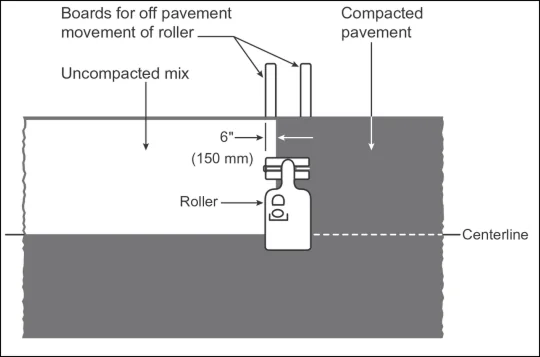
The transverse joint is then rolled transversely, with approximately 6 inches (150 mm) of the drum width on the newly laid material. This operation should be repeated with successive passes, each covering an additional 6 to 8 inches (150 to 200 mm) on the new mat, until the entire width of the roller is on the hot material. When the LJ is unconfined, this joint (edge) needs to be protected from the rollers. During transverse rolling, wooden boards the thickness of the compacted mat should be placed at the edge(s) of the pavement to give the roller a surface to drive onto and off the mat without causing the edge to deform (see Figure 127). The use of boards is recommended to avoid excessive shoving of the mix and to expedite the compaction process, but it may infringe on the adjacent pavement lane carrying traffic. If boards are not used, transverse rolling must stop 6 to 8 inches (150 to 200 mm) short of the outside edge to prevent damaging it, and the edge must be compacted later during longitudinal rolling.
Source: Asphalt Institute
Figure 127. Rolling the Hot Side of a Transverse Joint
Paving and compaction must be accomplished so that the completed transverse construction joint has a smooth transition across the joint and specification density has been achieved on both sides of the joint.