9. Joint Construction
9.3 Longitudinal Joints
Watch Video
The outline of this section follows the same sequence of steps as when an LJ is constructed:
- Placing the Unconfined Side (Edge)
- Rolling the Unconfined Side
- Placing the Confined Side
- Rolling the Confined Side
9.3.1 Placing the Unconfined Side (Edge)
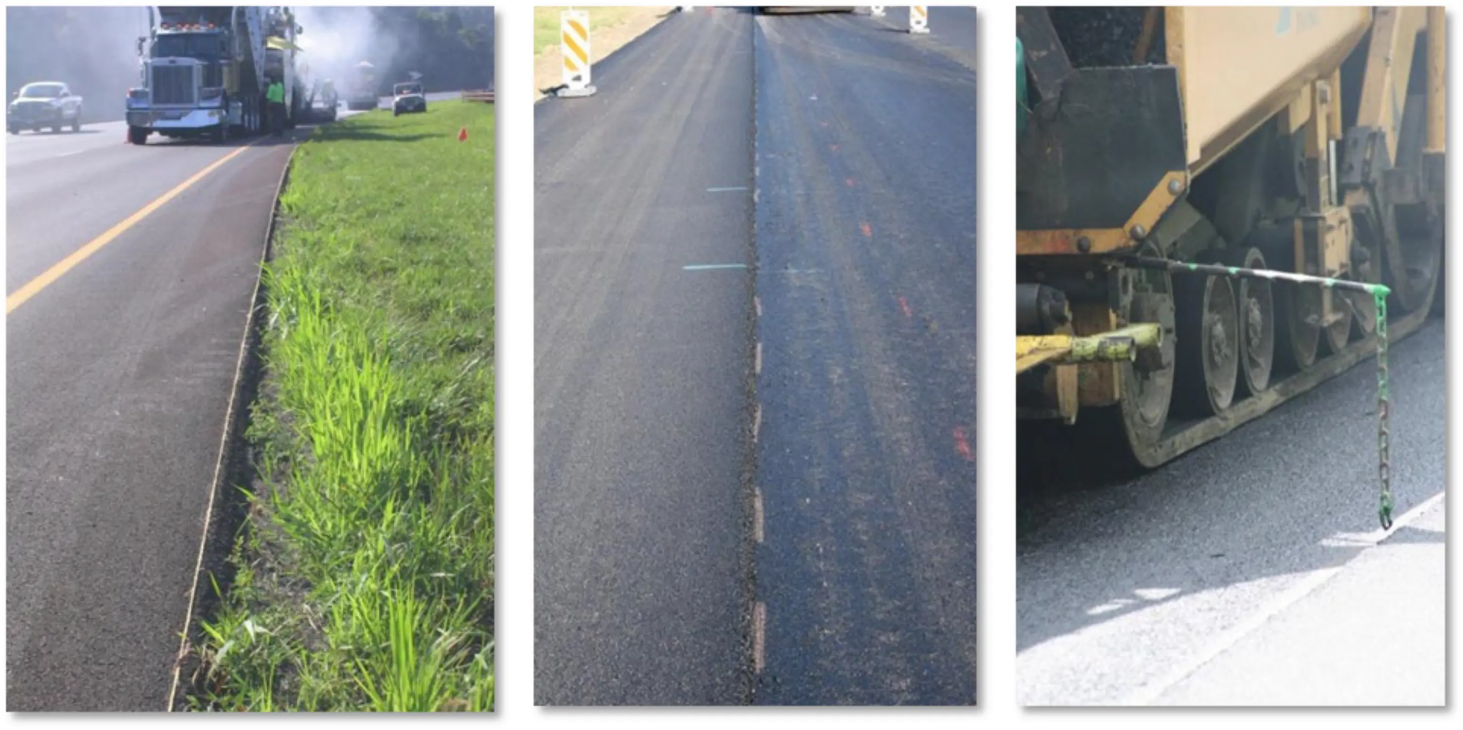
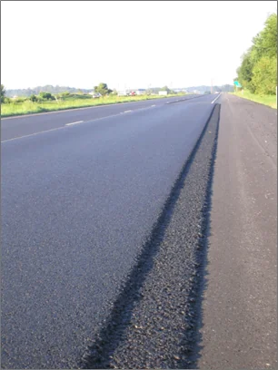
Proper construction of LJs starts with the laydown of the first lane. When the cold lane is placed, there is at least one unconfined edge of the mat. The unconfined edge must be constructed in a straight line. In the case of paving in a curve, the edge should be smooth. The use of a stringline and paint, with a guide mounted to the paver, should be employed to ensure a straight edge on the cold lane (see Figure 128). Edges that are not straight (see Figure 129) will be difficult to match with a consistent overlap (as discussed later in the chapter) when paving the hot side of the joint. This significantly increases the potential for low-density areas near the joint.
The use of a stringline and paint, with a guide mounted to the paver, should be employed to ensure a straight edge on the cold lane.
Source: Asphalt Institute
Figure 128. Paving in a Straight Line with Stringline, Skip Paint, and Guide on Paver
Source: Asphalt Institute
Figure 129. Not Paving Straight (or Smooth on a Curve) Makes It Impossible to Achieve a Consistent Overlay
9.3.1.1 Planning the Location of Longitudinal Joints
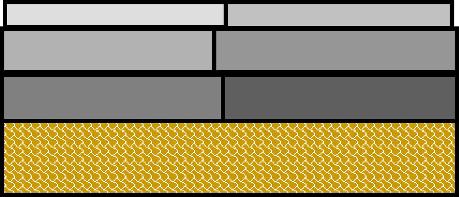
LJs should be located staggered (offset) from the underlying mat’s LJ by at least 6 inches (see Figure 130). If LJs are placed directly on top of each other, there will be a greater tendency for cracking to occur at the joint through the various lifts. Many specifications, including the DoD and FAA airfield specs, require the LJ to be offset a minimum of 1 ft from the LJ of the underlying layer.
Source: Asphalt Institute
Figure 130. Staggered Joints
When paving projects with multiple lifts, the location of LJs on all lifts should be planned with this minimum offset in mind. If the roadway or airfield feature is crowned at the center, it is desired for the location of the LJ on the surface lift to also be at the centerline. When possible, it is best to plan LJ locations so that the LJs on the surface lift do not fall within traffic wheel paths, recessed pavement markings, or striping. This is not generally possible on airfields.
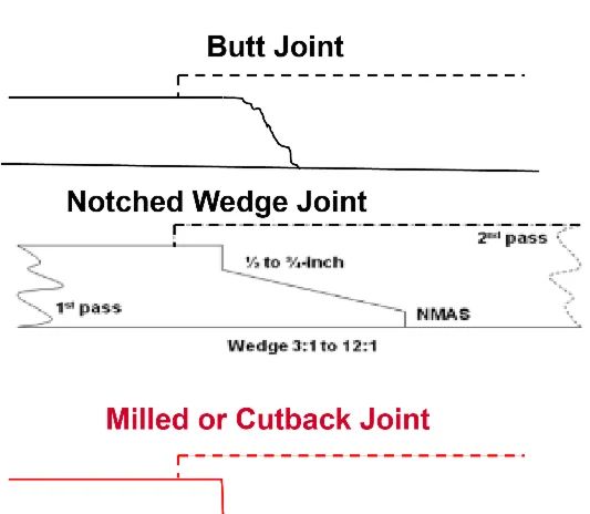
There are three types of conventional cold LJs, as seen in Figure 131: butt, notched-wedge, and milled or cutback. Each will be described in the next three sections.
Source: Asphalt Institute
Figure 131. Different Types of Longitudinal Joints
9.3.1.2 Butt Joints
The butt joint is the most common type of LJ. While placing the unconfined side, butt joints start with a fairly vertical edge, assuming the end gate is set down properly by riding on the existing surface. Full screed vibration (leaving the screed vibrator on) assists mix consolidation at the bottom of the joint. After the mat is placed and during compaction (discussed in the next section), the mat’s edge tends to seek its own angle of repose (less vertical).
Figure 132 shows the poor practice of setting the end gate higher, which allows the mix to flow under the end gate, leading to very low density after compaction on the unconfined edge. Setting the end gate properly, firmly seated on the existing pavement surface, prevents this.
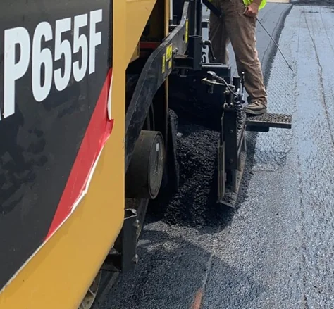
Source: Asphalt Institute
Figure 132. Poor Practice—End Gate Not Set to Be Seated on Existing Surface
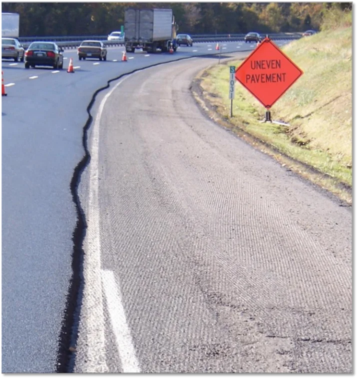
Unsupported butt joints of substantial thickness opened to traffic may create hazardous drop-off conditions for motorists. The Manual on Uniform Traffic Control Devices (MUTCD) provides recommendations for signage to warn motorists of unexpected conditions. Where excessive drop-offs are necessary, it may be best to close the adjacent lane or use a notched-wedge joint (discussed next).
9.3.1.3 Notched-Wedge Joints
The notched-wedge joint technique (see Figure 133) was originally designed to provide traffic a safer transition when changing lanes between the newly paved surface and the lower, existing surface. Many overlay specifications do not allow a pavement edge drop-off to remain exposed to traffic and require adjacent lanes to be completed by the end of the day. This safety feature increases production by allowing paving to continue the entire paving shift in one lane, instead of moving back at mid-shift and switching traffic control to pave an adjacent lane.
Source: Asphalt Institute
Figure 133. Notched-Wedge Joint with Taper at Top and Bottom of Wedge
The initial pass has a tapered face up to 1 ft (300 mm) in width, with a slope ranging from 3:1 to 12:1. The wedge configuration should include a notch at the top and a notch at the bottom. Notched depths of at least one NMAS are recommended.
Agencies that have adopted the use of the notched wedge generally note an increase in joint density and an improvement in the long-term performance of their LJs when compared to the butt joint. This is not the case when compared to the cutback joint. The notched wedge provides lateral support for the unconfined edge under compaction while increasing the bonding surface area between the two mats.
It is important to provide some type of compactive effort to the wedge material. Figure 134 shows a device that forms the wedge and provides some initial compaction through extrusion and vibration from the screed.
Source: Asphalt Institute
Figure 134. Notched-Wedge Device that Forms and Compacts through Screed Vibration
In Figure 135, a tow-behind wheel compactor and a tow-behind, self-vibrating plate compactor are shown.
Source: Asphalt Institute
Figure 135. Two Devices for Compacting the Wedge of a Notched-Wedge Joint
9.3.1.4 Milled or Cutback Joint
A milled or cutback joint (referred to as the cutback method) is created by physically removing 2 to 6 inches of material at the unconfined edge of the recently laid mat with either a cutting wheel (also known as a pizza cutter) or a milling machine. The cutback method offers two advantages to the LJ: providing a near-vertical edge to compact against and eliminating the area of low-density material at the unconfined edge of the first mat (see Figure 136).
Source: Asphalt Institute
Figure 136. Key Aspects to Constructing a Durable Longitudinal Joint
Both the FAA and DoD airfield paving specifications require cutting back the joint with a cutting wheel. While the cutting wheel is not common on roadway projects due to traffic control challenges and slowing production, milling back the joint is routine in Michigan for DOT work where the contractor is compensated for over-paving the joint by up to 2 inches (measured from the top of the mat).
The following standard practices should be followed when cutting back the LJ with a cutting wheel:
- The amount of material that should be cut back is generally determined by the specification. The DoD airfield specification currently says to cut back between 3 and 6 inches, while the FAA specification currently says a maximum of 3 inches.
- The cutting wheel is typically about 10 inches in diameter, with the cutting angle being about 10 to 20 degrees from vertical.
- The mix is cut back while it is still warm (120 to 140 °F) to provide the cleanest cut. This is known as the temperature sweet spot.
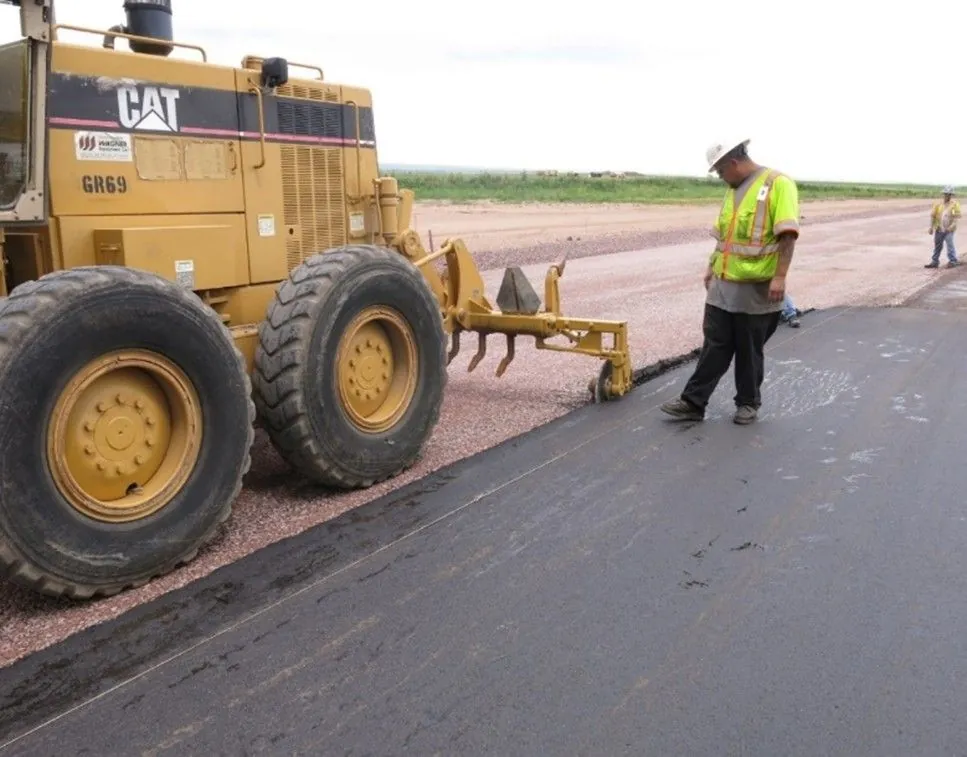
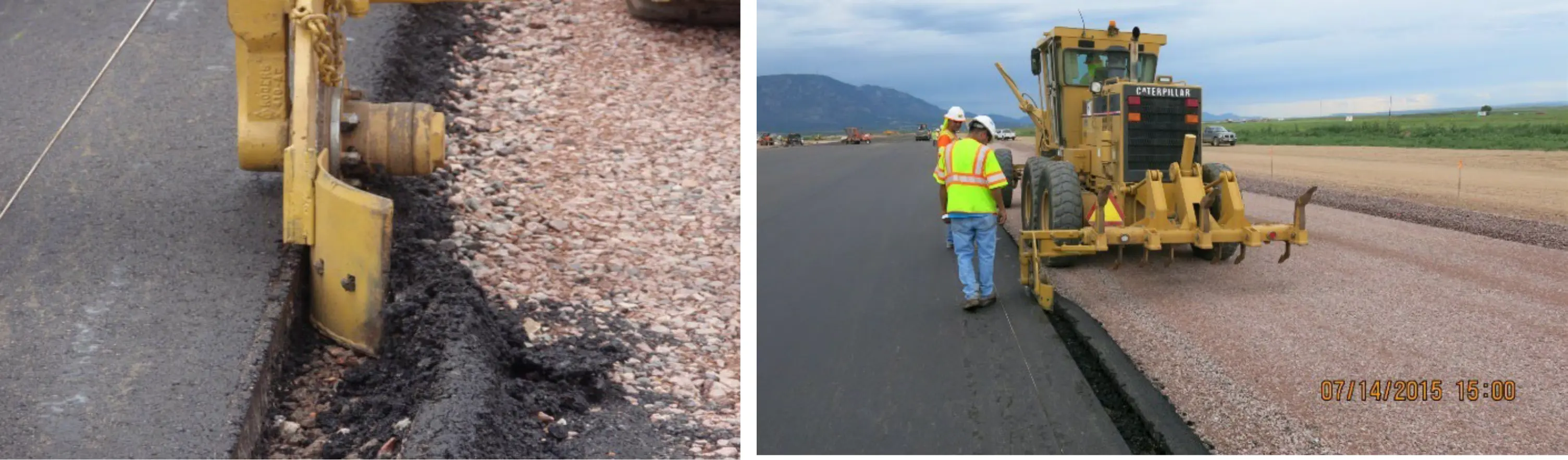
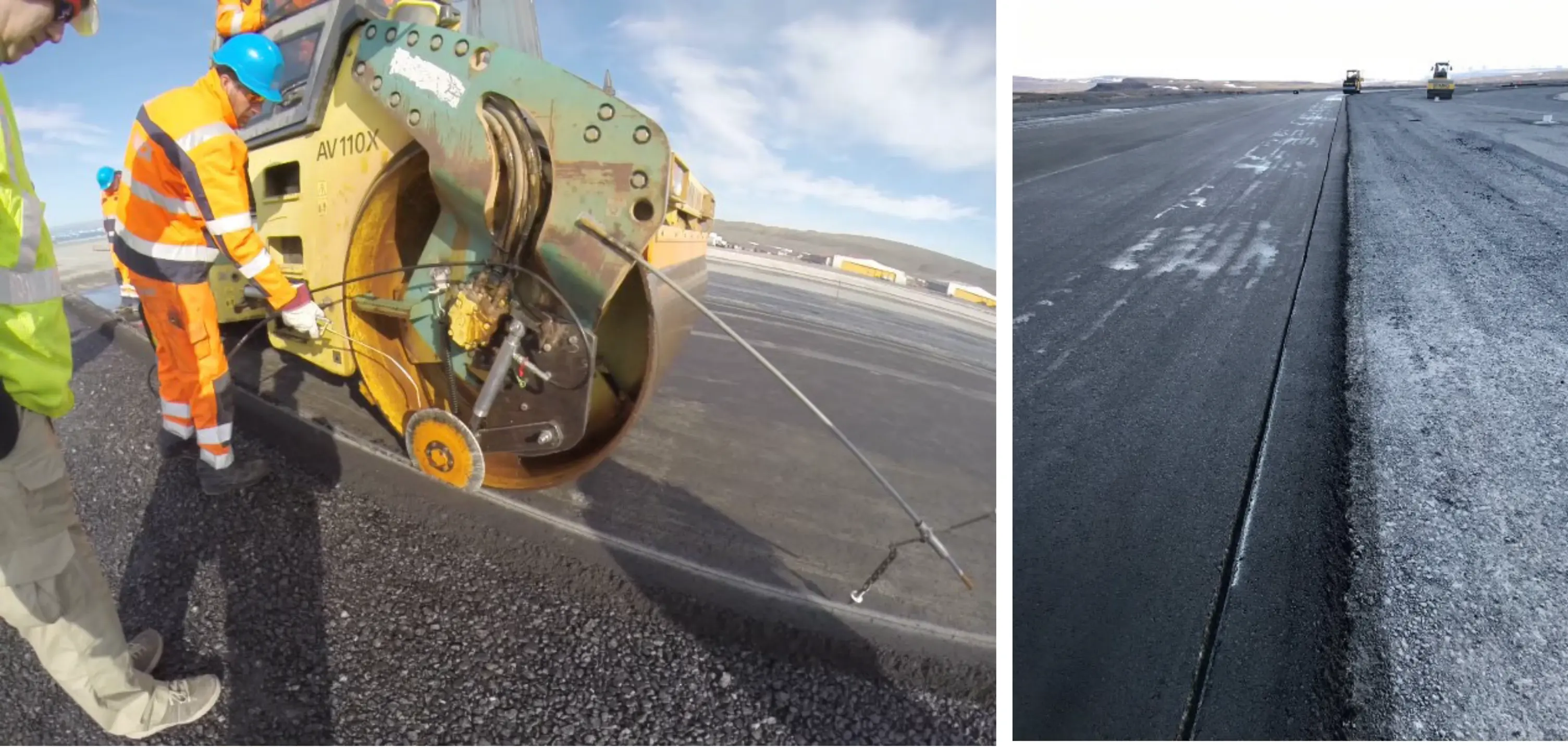
- The cutting wheel can be mounted on a steel-wheel roller (see Figure 137 and Figure 140) or on the blade or rear ripper of a motor grader (see Figure 138). Mounting on a short-wheelbase vehicle such as a skid steer should be avoided. If mounted on a roller, the cutting wheel can be operated on the newly paved surface. If mounted on a grader, the cutting wheel can be operated on the adjacent lane to be paved to avoid rutting on the newly paved mat that has not fully cooled.
- The trimmings should be carefully and completely removed prior to placing the hot lane. A kickout plate that pushes the trimmings away from the joint can help (see Figure 139). Any loose material must be removed, by hand if necessary. All the trimmings can be collected and used as RAP.
- It is critical that the cuts are straight and without wander to facilitate a consistent overlap on the cold mat when the hot mat is placed. Using a stringline for reference, skip paint, and a guide mounted on the front of the roller or grader for the operator to follow can help ensure a straight cut (see Figure 137, Figure 138, and Figure 140).
- No water and especially no release agent should be used to assist cutting, as this will deter the necessary bonding of the two mats.
- The cut should provide a clean, sound, near-vertical face for the full depth of lift.

Source: U.S. Army Corps of Engineers
Figure 137. Cutting Wheel Mounted on a Roller
Source: U.S. Army Corps of Engineers
Figure 138. Cutting Wheel Attached to Rear Ripper of a Grader
Source: U.S. Army Corps of Engineers
Figure 139. Kick-Out Plate Aids in Removing the Cutback Mix
Source: U.S. Army Corps of Engineers
Figure 140. Stringline, Paint, and a Mounted Guide Allow Straight Cutting
9.3.2 Rolling the Unconfined Side
Attention is key when rolling the unconfined joint because density across the mat is typically lowest at the unsupported edge. The unconfined edge should be compacted with a steel-drum roller as soon as possible while the mat is hottest.
Attention is key when rolling the unconfined joint because density across the mat is typically lowest at the unsupported edge. The unconfined edge should be compacted with a steel-drum roller as soon as possible while the mat is hottest.
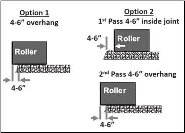
There are two recommended options for a rolling pattern of the unconfined joint to optimize density. Option 1 is to roll the first pass with the steel drum overhanging the mat edge 4 to 6 inches (100 to 150 mm). More than a 6-inch overlap can cause too much force at the mat edge, resulting in excessive rolldown. Targeting less than a 4-inch overlap may result in the drum occasionally cutting into the edge of the unconfined joint. Option 2 is for the first pass to stay inside the mat edge 4 to 6 inches and the second pass overhanging the edge 4 to 6 inches. Both options are illustrated in Figure 141.
Proponents of option 2 believe there is less lateral movement of the unsupported edge under the mat. A concern with option 2 is that a stress crack can be induced at the edge of the steel drum during its first pass (4 to 6 inches inside the LJ). Such a potential stress crack may not be visible until months or years later. Proponents of option 1 are concerned with the potential for this stress crack and/or believe it is best to roll the edge when hottest.
Source: Asphalt Institute
Figure 141. Two Options for Compacting the Unconfined LJ
The following are factors to consider in deciding between option 1 and option 2:
- Density measurements close to the unsupported edge.
- Mix properties or other elements that may create excessive lateral movement.
- Excessive rolldown at the mat edge.
- Potential for stress cracks with option 2.
9.3.3 Placing the Confined Side
The following are three key considerations that should be understood when placing the hot side of the LJ that will be covered in this section:
- Tacking/bonding the near-vertical face prior to placement.
- Having sufficient rolldown mix to avoid rollers bridging on the cold mat.
- Achieving the proper overlap of the hot mat over the cold mat.
9.3.3.1 Tacking the Vertical Face
Before placing the hot lane, the cold near-vertical joint face should receive at minimum a heavy application of emulsified tack coat material, no matter whether it is a butt or cutback joint. Even a notched-wedge joint will benefit from being tacked as long as the material does not bleed up into the surface.
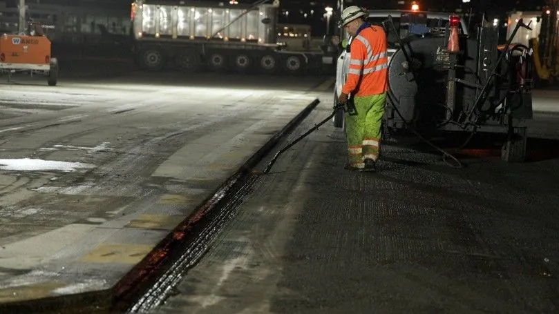
A more substantial treatment of the cold joint face is the application of an asphalt binder, or better yet, a rubberized joint sealant (also called joint adhesive), as seen in Figure 142. Spraying hot asphalt binder on the joint face results in more residual asphalt relative to an asphalt emulsion. The use of a rubberized joint adhesive provides the best bond at the cold joint. Many States require either the vertical face be painted with an asphalt binder or a rubberized joint adhesive be applied to improve the durability of the joint.
Source: National Asphalt Pavement Association
Figure 142. Joint Adhesive Being Applied to the Cold Joint Face
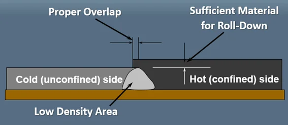
9.3.3.2 Sufficient Material for Rolldown
Figure 144 shows one of the key aspects to constructing a durable LJ is having sufficient material for rolldown. Material rolldown was discussed in Section 7.5, with the general rule of thumb being 25 percent but varying depending on the mix. The height of the uncompacted hot mat is established based on the rolldown factor. It is critical that there is sufficient thickness on the hot side of the joint for complete rolldown and compaction before the steel-wheel roller compacts down to the cold mat. If insufficient material is placed, “bridging” of the steel roller on the cold mat will occur before complete densification on the hot side is achieved. This creates a joint doomed to failure with the low-density material on the hot side of the joint, resulting in an area permeable to water and air with poor durability. A joint completed with insufficient mix thickness may initially look better but will perform worse than a well-compacted joint.
It is critical that there is sufficient thickness on the hot side of the joint for complete rolldown and compaction before the steel-wheel roller compacts down to the cold mat.
Projects with ride or smoothness specifications will require the use of mobile reference beams or skis (see Section 7.4.2.1) on the lower lifts. If the smoothness specification is met in the last intermediate lift before the surface is applied, then the surface can be paved at the required thickness with a matching grade sensor. If the surface layer requires the use of a ski to meet the final smoothness specification, the ski should only be used on the cold side of the joint and a matching grade sensor used on the hot side of the joint. Using the ski on the hot side of the joint will result in a nonuniform thickness across the joint, which can lead to lower density along the joint. This is because the ski averages the mat thickness required over the length of the ski (30 to 40 ft) and may not always provide the correct amount of mixture for the joint.
Using the grade sensor on the paver as a joint matcher device that takes a single reading just in front of the augers does a better job of getting the correct height of material at the joint. The joint matcher measures the mat thickness continuously along the joint and provides the required amount of material at each precise location. Section 7.4.2.2 covers joint-matching devices.
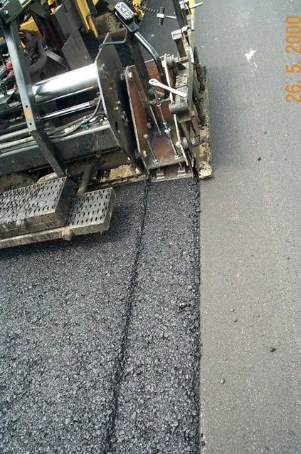
9.3.3.3 Proper Overlap
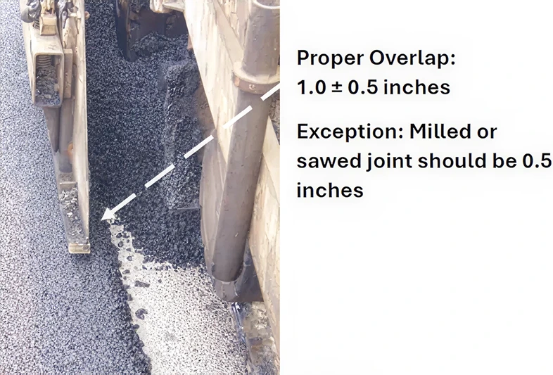
The other key aspect to constructing a durable LJ is to consistently maintain the correct amount of overlap from the hot mat onto the cold mat (illustrated in Figure 143). The correct amount of overlap is 1±1/2 inch (25±12.5 mm) for a butt joint. If the joint is cut back, the correct amount of overlap is less, targeting 1/2±1/2 inch (12.5±12.5 mm). As mentioned earlier, this correct overlap will be difficult to maintain if the first pass was not paved straight (or smooth for a curve). The screed operator should closely follow the joint line and monitor the overlap closely to maintain this tight tolerance. A variable-width screed (if equipped) can be helpful to move the screed in or out as necessary.
Not everyone may agree the correct amount of overlap is as recommended above, but there is no debate that some overlap is needed. Without targeting some overlap, there will be instances where there will be a gap at the joint, resulting in low density and a likely crack.
Luting (bumping) the overlap material off the cold mat and onto the hot mat is not necessary if the proper overlap (as prescribed in the above paragraph) is maintained. The small amount of overlap will not create much loose material at the surface after rolling, and that material will quickly ravel away.
Source: Frank Colella
Figure 143. Proper Overlap When Placing the Confined Side of a Longitudinal Joint
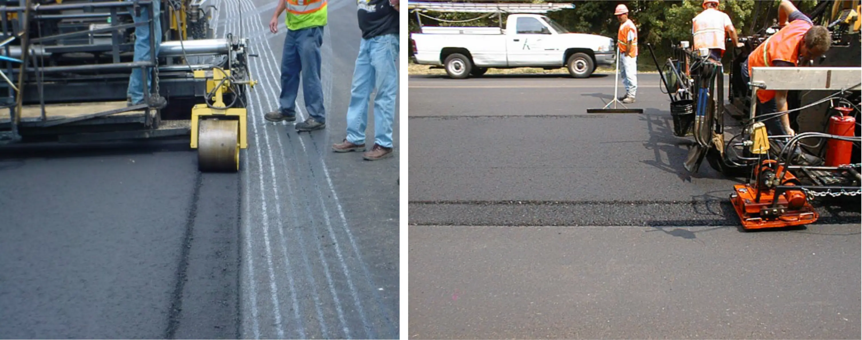
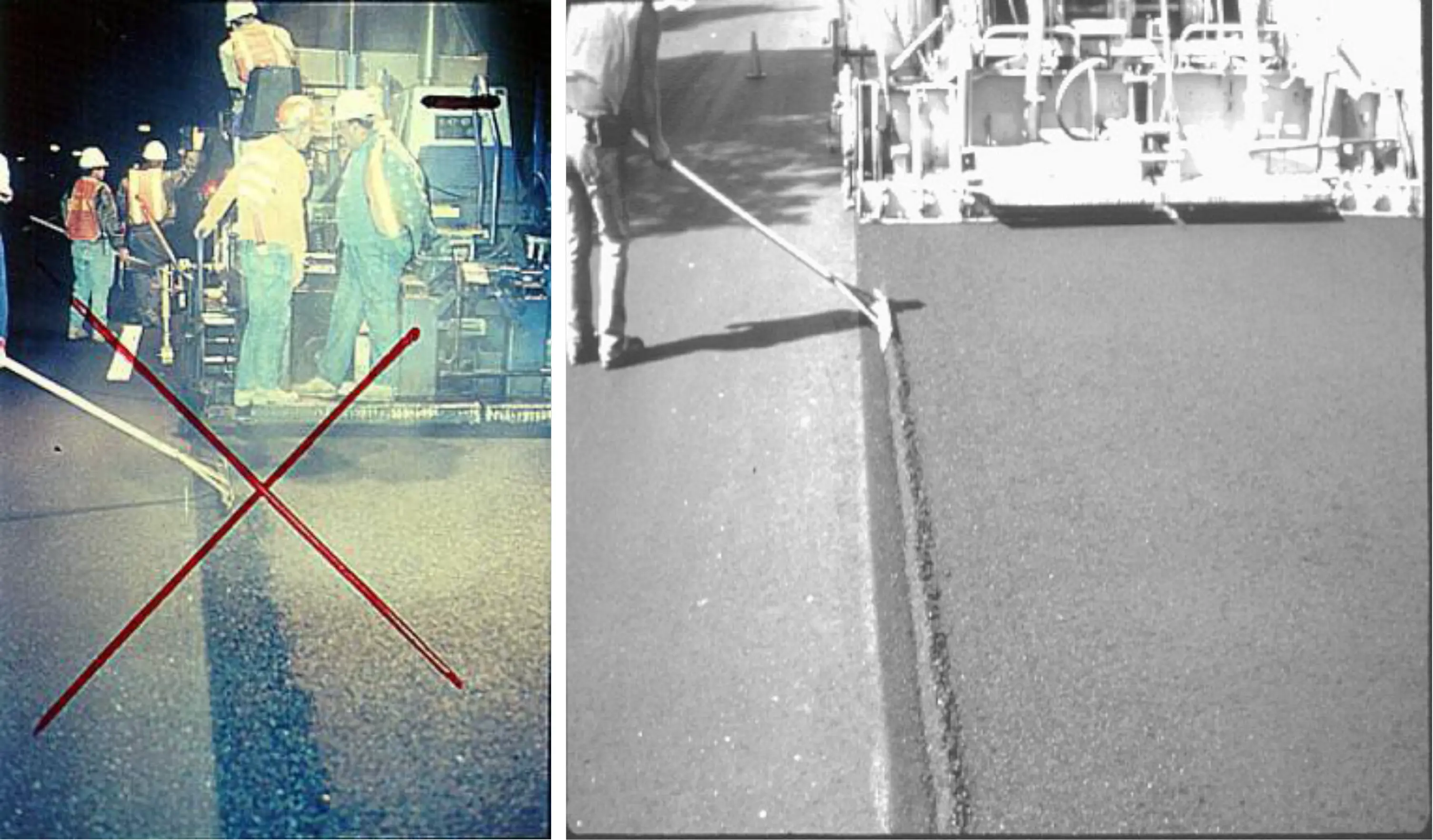
If bumping of the overlap material is done, it is crucial that the overlap material only be bumped just across onto the hot mat and not pushed farther. The rolldown material just on the hot side of the joint should not be disturbed; it must remain to achieve proper density. Aggressive luting that extends across the hot joint must be avoided as it will remove the rolldown material just on the hot side of the joint, resulting in low density as described earlier in this section. This can also cause segregated material on the surface. Improper luting of the LJ is shown in the left picture of Figure 144, while proper luting is shown in the right picture.
Aggressive luting that extends across the hot joint must be avoided as it will remove the rolldown material just on the hot side of the joint, resulting in low density.
If done carefully and correctly, luting the overlap can be beneficial. If done incorrectly, luting the overlap can cause severe joint failure.
Source: Asphalt Institute
Figure 144. Improper Luting of the LJ (left), which Starves the Hot Side of Rolldown Material,
and Proper Luting of the LJ (right)
Another consideration of whether to lute or not is safety. On roadway projects, traffic in adjacent lanes can make the luting operation very dangerous. This is not a concern for airfield projects where the entire area is closed to traffic.
Broadcasting extra material onto the hot lane should be avoided as it will result in coarse aggregate on the surface that can pop out over time, especially on airfields where FOD is a major concern. Improper broadcasting and improper luting across the joint is shown in Figure 145.
Source: Asphalt Institute
Figure 145. Improper Broadcasting and Luting across the LJ
9.3.4 Rolling the Confined Side
The confined joint should be compacted with the first pass of a steel-drum roller on the hot mat, with the edge of the drum about 6 to 12 inches (150 to 300 mm) off the LJ. The second pass is then applied by overlapping onto the cold mat by 3 to 6 inches (75 to 150 mm). The first pass creates an uncompacted strip 6 to 12 inches wide where any lateral movement pushes extra mix into this strip. The second pass then compacts this uncompacted strip with the full weight of the roller.
The primary reason for staying off the joint on the first pass is to avoid bridging the roller drum on the cold edge. As described previously in Section 9.3.3.2, “bridging” results in no further compactive effort being applied. Staying off the joint 6 to 12 inches slightly migrates the mix laterally into the joint, which results in a little extra mix and higher density in this area. This recommended rolling pattern for compacting confined joints also ensures the first and second passes occur with most of the roller on the hot mat.
Rubber tire rollers, especially vibratory rubber tire rollers, have proven to be very effective in optimizing density at the confined side of the joint.